Kai's Mac Classic Reloaded is exciting! I have some chips from bombed SEs which I am anxious to put to use once I have a bit more time and space on the soldering bench. But I feel it would be a big shame if the project sort of went out the door with the original RAM card when we can make something less expensive, more reliable, and with less solder joints.
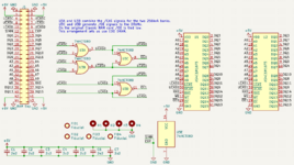
So this RAM card is (as usual) a collaboration with Garrett Fellers of Garrett's Workhop. On the card, I'm using two 1Mx16 DRAMs which can be FPM or EDO. There is a total of 4 MB of RAM on the card although only 3 MB is used in a regular Mac Classic. The two RAM chips can be had for $1-3 each. The Classic RAM card has three banks of RAM (two soldered, one set of SIMMs) so we have to sort of combine the /CAS signals for the two 512 kB banks so that they go to just one chip/bank. The signals normally going to the SIMMs can be sent to the other 1Mx16 DRAM unchanged since the two SIMMs have the same capacity and addressing as one of the chips on my board. Since there is an extra megabyte of RAM on the board, it would be possible to modify the Mac Classic with some jumpers that would allow the omission of the eight onboard RAM chips and all of the system RAM to come from the card. This is obviously cheaper if you're building your own Classic, plus less soldering. Board is two layers, made possible by the compact layout, etc. Effort has been made to ensure good paths for the return current despite the two-layer construction. The whole thing is not too much bigger than the connector itself (which doesn't have too many ground pins) so I don't anticipate any issues going to two layers.
Garrett and I have our hands full with a very long list of stuff to do and I didn't wanna add another thing on the Garrett's Workshop to-do list. So Garrett Bunge has kindly agreed to put some together for testing purposes. (What a coinky-dink!) Unfortunately the card is just so simple that we are not recruiting more testers at this time; the only possible problem would just be a wiring mistake so we just need to put the card together and make sure it works. The card will eventually be for sale for something like $20-30 including shipping anywhere in the US.
Board rendering and schematic:


Source: https://github.com/garrettsworkshop/MacClassicRAMCard
Current Project Status - July 6, 2021
50 units are in production. Should be completed and ready for sale in the next few weeks.
Old content from original post:
So this RAM card is (as usual) a collaboration with Garrett Fellers of Garrett's Workhop. On the card, I'm using two 1Mx16 DRAMs which can be FPM or EDO. There is a total of 4 MB of RAM on the card although only 3 MB is used in a regular Mac Classic. The two RAM chips can be had for $1-3 each. The Classic RAM card has three banks of RAM (two soldered, one set of SIMMs) so we have to sort of combine the /CAS signals for the two 512 kB banks so that they go to just one chip/bank. The signals normally going to the SIMMs can be sent to the other 1Mx16 DRAM unchanged since the two SIMMs have the same capacity and addressing as one of the chips on my board. Since there is an extra megabyte of RAM on the board, it would be possible to modify the Mac Classic with some jumpers that would allow the omission of the eight onboard RAM chips and all of the system RAM to come from the card. This is obviously cheaper if you're building your own Classic, plus less soldering. Board is two layers, made possible by the compact layout, etc. Effort has been made to ensure good paths for the return current despite the two-layer construction. The whole thing is not too much bigger than the connector itself (which doesn't have too many ground pins) so I don't anticipate any issues going to two layers.
Garrett and I have our hands full with a very long list of stuff to do and I didn't wanna add another thing on the Garrett's Workshop to-do list. So Garrett Bunge has kindly agreed to put some together for testing purposes. (What a coinky-dink!) Unfortunately the card is just so simple that we are not recruiting more testers at this time; the only possible problem would just be a wiring mistake so we just need to put the card together and make sure it works. The card will eventually be for sale for something like $20-30 including shipping anywhere in the US.
Board rendering and schematic:

Source: https://github.com/garrettsworkshop/MacClassicRAMCard
Current Project Status - July 6, 2021
50 units are in production. Should be completed and ready for sale in the next few weeks.
Old content from original post:
I haven't had a chance to add a LICENSE file to the repo but we will be dual-licensing under the same simple scheme we always use at GW. Commercial use under CC-BY-SA is allowed, just remove the "Garrett's Workshop" text since we would rather compatible boards not masquerade as genuine products. You can put your own logo/company name on instead! If you're just making 'em for you and friends, you can use the gerbers as-is with the Garrett's Workshop branding under CC-BY-NC-SA.
Board photo:

Schematic (dead simple!):

Current Problem - Connector Sourcing
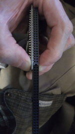
The biggest current problem is the connector. I have intentionally put a different type of connector on the board than comes on the original card. The original connector is $7. I wanna sell the card for $25 or something, so too much to spend on just a connector. Therefore I have put a more ordinary right-angle type connector on the board instead. Problem is that 2x22 pin size female 2.54mm pitch right angle header connectors are very, very uncommon. So we will have to double up the connectors. I think it'll work. Maybe... 2x17 (IBM floppy) + 2x5 (JTAG, etc.), 2x8 + 2x14, 2x10 (JTAG, etc.) + 2x12. Those are (owing to their respective functions) the most common sizes that add up to 2x22. Any good? We might have to shave down the edges slightly but these sizes are really cheap, as low as $0.25 each. Or is just worth the $7 for the original connector type? Typically for products like this, the selling price has to be 3x parts cost to cover shipping, manufacturing scrap, returns/defective products, etc. and make a little money. But we can probably just like ignore that type of analysis lol and tack $7 on the price to pay for the connector and it'll be fine since the product is so simple there aren't lots of opportunities for stuff to go wrong. What's best?
Board photo:
Schematic (dead simple!):
Current Problem - Connector Sourcing
The biggest current problem is the connector. I have intentionally put a different type of connector on the board than comes on the original card. The original connector is $7. I wanna sell the card for $25 or something, so too much to spend on just a connector. Therefore I have put a more ordinary right-angle type connector on the board instead. Problem is that 2x22 pin size female 2.54mm pitch right angle header connectors are very, very uncommon. So we will have to double up the connectors. I think it'll work. Maybe... 2x17 (IBM floppy) + 2x5 (JTAG, etc.), 2x8 + 2x14, 2x10 (JTAG, etc.) + 2x12. Those are (owing to their respective functions) the most common sizes that add up to 2x22. Any good? We might have to shave down the edges slightly but these sizes are really cheap, as low as $0.25 each. Or is just worth the $7 for the original connector type? Typically for products like this, the selling price has to be 3x parts cost to cover shipping, manufacturing scrap, returns/defective products, etc. and make a little money. But we can probably just like ignore that type of analysis lol and tack $7 on the price to pay for the connector and it'll be fine since the product is so simple there aren't lots of opportunities for stuff to go wrong. What's best?
Last edited:


