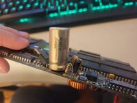
I have a Radius Plus Accelerator that came in my Mac Plus, but there is an obviously bulged cap on it and I want to replace the tantalum that I read somewhere is prone to blowing up. The cap that is bulged on the accelerator board has a mark in the side that makes it so I can't tell if its supposed to be 1000uf, 1800uf or something else. The only other two I've seen online have a different cap where this one is, I've seen one 470uf and another I couldn't make out, but they both were on their side instead of this one being straight up. Is it also safe to replace that tantalum cap with a normal electrolytic? I think I have a 10 or 16v 150uf cap to replace it with already. I do have the software for it, but does anyone have a manual for this? I don't know how you get the Plus board into the computer easily with it in there, I had to slightly bend the side with the rails to pull it out from the bottom because said cap hits against the internal metal frame of the Plus (probably why later versions had it on its side?) as well as where the grounding springs go on the main Plus board. If anyone has any info about these boards it would be greatly appreciated. I've attached a picture of the cap with the mark on it so maybe someone can recognize it.
Mac Plus Radius Accelerator Plus help
- Thread starter Kothnaaken
- Start date
You are using an out of date browser. It may not display this or other websites correctly.
You should upgrade or use an alternative browser.
You should upgrade or use an alternative browser.
A 68020 in a Mac Plus? Whoa! That's cool.
How many MHz is this running at? Where/how does the board connect to the main logic board?
How many MHz is this running at? Where/how does the board connect to the main logic board?
Hi @Kothnaaken! ")

Could you please take pictures of the top and bottom of the whole accelerator board? That will help us a lot to help you.
Could you please take pictures of the top and bottom of the whole accelerator board? That will help us a lot to help you.
That would be a Radius Accelerator 16, which adds a 16MHz 020 to a Plus. You can stick an FPU in there too if you want.
It attaches to the CPU with a Killy clip.
I had one of these NIB a few years back but, after really enjoying doing a clean install from scratch and playing with it for a while, I sold the Plus. (I prefer faster 68000 accelerators in 68000 machines for maximum throwback compatibility, a matter of personal taste.)
The board looks slightly different from the Radius Accelerator 16 I have seen around. Hence, I asked @Kothnaaken to take pictures to see the whole board.
Here's the top and bottom. Going off the copyright date of 87 and the fact mine's serial number and board both say 87 on it makes me think that this is an early one. Are the serial numbers of the boards after the year in sequence?
Attachments
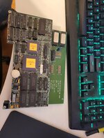
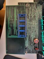
The problem cap is the tantalum in the lower right hand corner. If it's shorted the Mac Plus will "Flup" and not start up.
See here: https://68kmla.org/bb/index.php?threads/repairing-a-radius-16-accelerator-plus.1167/
See here: https://68kmla.org/bb/index.php?threads/repairing-a-radius-16-accelerator-plus.1167/
Last edited:
I saw @360alaska's post at the 68kmla. It could be that, @Kothnaaken. A multimeter can help you see if anything works in those mentioned areas.
 68kmla.org
It could be that, @Kothnaaken. A multimeter can help you see if anything works in those mentioned areas.Repairing a Radius 16 Accelerator (Plus)
Hello all, I just want to share my experience regarding a newly acquired Mac Plus. It was flup-flup-fluping when I bought it and to my surprise it had the Radius 16 accelerator! I uninstalled the Radius 16 and discovered that the Mac worked fine without it. After troubleshooting, I discovered...
I did intend on replacing the tantalum cap as well, though the big electrolytic is slightly bulged on the bottom and I want to replace it before it gets worse and starts leaking. That gouge in the electrolytic makes it so I can't see if it's 1000 or 1800 or similar uf and I don't have an LCR meter to test it just yet.
Small update: I did test the tantalum with my multimeter and sure enough it is shorted. I tried testing the diode but on mine it is in a very awkward spot to test, one of the solder points is under a coil and its too closely mounted to the board in order to test it above, I probably will end up replacing it regardless.
Small update: I did test the tantalum with my multimeter and sure enough it is shorted. I tried testing the diode but on mine it is in a very awkward spot to test, one of the solder points is under a coil and its too closely mounted to the board in order to test it above, I probably will end up replacing it regardless.
Yeah, it is a good idea to replace it. Have you checked out TinkerDifferent's Discord? It is nice to document here. Discord is quicker to get help if needed.
Another small update I found out and I'm glad I did a bit of testing is that the springs on the bottom are not both ground, one of them is but one of them seems to be for power. Does anyone have any idea of where those springs are supposed to go on the Plus board for when I get this recapped?
Yet another update: I caved and bought a cheap LCR meter off Amazon and took that cap which is quite bulged on the bottom off and put it in my LCR meter, it reads about 1300uf which going off the 10% error roughly I notice on this meter I assume is supposed to be 1200uf or so? It doesn't look like it was supposed to say 1200, but its definitely not saying 1500uf. I plan on going out to get the caps and the diode I need to replace tomorrow.
Although Radius was a well-respected Macintosh products developer back in the day, it certainly looks like a case of "what NOT to do" when it comes to accelerator board design. Look at the size of that cap... Holy Cow!

I did end up figuring out it was a 1000uf cap there. I think for the later revisions they wised up about that since they put a 470uf cap there but sideways so it fit much better. Also one that has a readable sleeve unlike that.