I can try to update the above linked model to have the proper screw mount locations for 2023.10a version of the BlueSCSI v2
I took a peek at the model you just linked. Let’s call it the jonschwenn model. It definitely looks to have been designed with FDM printing in mind. However, I see a few issues when I pulled it into TinkerCAD alongside yours. . .
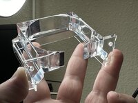
The PCB mounting holes would need to be adjusted as you mentioned, but when I lined up the expansion port screw holes, they are not even close. I don’t know how this could have fit an SE chassis at all. I just printed yours and it lined up perfectly.
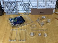
Also, the jonschwenn model has some missing solids. It appears to be modeled with walls first, then a solid block near the chassis mount holes, but the blocks are missing upon import into TinkerCAD. It’s another example of STL file breakdown. Maybe it’s an easy import/fix/export from Prusa slicer, but the dimensions of those chassis mount holes are a concern.
On the plus side, I do like that has no overhangs and should print without supports. There is the bridge over the SD card slot, but a bridge that size should be fine. I also especially like the thin wall facing the back. This will have better transparency with T-Glase or other clear FDM filaments, as it minimizes the number of layer/perimeters that obscure the light.
I might play with this since I can print another bracket without much issue. The changes I would make:
1. Fix the mounting holes for the chassis. It just seems out of proportion and needs to be wider.
2. Fix the mounting holes for the latest BlueSCSI PCB. It probably only needs one hole in the middle since the board is already captured side to side.
3. Add a top surface over the SD card slot using 45-degree from the back edge. This will give it a little more back to front depth along the back face so that you don’t end up with a gap along that top edge.