Mod: Quadra 660AV 2 MB VRAM Upgrade

Zane Kaminski

Administrator
Staff member
Founder
Sep 5, 2021
372
610
93
Columbus, Ohio, USA
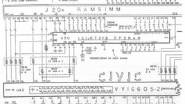
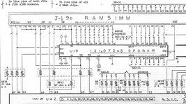
Has anyone tried piggybacking another set of VRAM chips on top of the ones already mounted on the motherboard? On the 840AV, most of the signals are shared between the soldered VRAM and expansion VRAM. The only different pins are separate /RAS and /SE lines on the CIVIC video chip which are pinned out to the sockets on the 840AV. I’m thinking on my 660AV I can just wire a second set of VRAMs in parallel except for /RAS and /SE and run those to the CIVIC.

I’ve attached some pictures from the 840AV Bomarc schematic showing the wiring for the “X” and “Y” VRAM banks. I should be able to duplicate this on the 660AV with piggybacked chips and only four bodge wires.

But will the ROM / Mac OS recognize the extra VRAM?
 

Attachments

  • 4D69B60E-0F16-45AA-B9E4-7F577A1C55C4.png
    4D69B60E-0F16-45AA-B9E4-7F577A1C55C4.png
    242.9 KB · Views: 132
  • B16BADEE-F114-448E-9DDA-ABD879A00F41.jpeg
    B16BADEE-F114-448E-9DDA-ABD879A00F41.jpeg
    156.3 KB · Views: 126
  • Like
Reactions: iPhil64 and alxlab

Zane Kaminski

Administrator
Staff member
Founder
Sep 5, 2021
372
610
93
Columbus, Ohio, USA
Alright, 660AV has been recapped and I think it’s working perfectly. It was missing a SCSI termination voltage regulator somehow so I borrowed one from another board. Once I test a bit I’m gonna assemble the double VRAM stacks and replace em. I’m using 70ns VRAM in since I have it on hand and maybe 80 ns would limit overclocking... probably not but I dunno.
 
  • Like
Reactions: iPhil64

trag

Tinkerer
Oct 25, 2021
280
133
43
@Zane Kaminski ROM Apple part numbers on the Q840AV are 341S0923 and 341S0924. Does the 660AV use the same ROM? If so, I would guess that the chances of success are excellent. I guess they could have programmed in a machine ID branch, but why would they?
 
Last edited:

Zane Kaminski

Administrator
Staff member
Founder
Sep 5, 2021
372
610
93
Columbus, Ohio, USA
Currently Garrett is assembling the VRAM stacks which we are going to swap onto the board. Here’s some pics

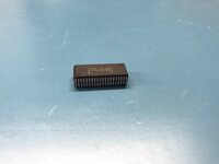
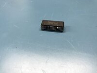
Bending out the leads:
36CF011D-B08A-4675-9245-ED561B130768.jpeg
148068ED-90DF-49B9-A0C3-0F85EF8E7597.jpeg
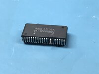
Stacked atop unmodified SOJ:
1E0B2893-63BE-4B56-8C86-D442C3D4F219.jpeg
Separating the RAS and SE:
368D8C42-8FB5-4D6D-81B7-92FD05B40CFD.jpeg
Soldered:
F2E5A6B4-D329-4F1C-9173-9A6D302D0EC1.jpeg

All credit for stacking these things so meticulously goes to my best friend Garrett Fellers. (Maybe one day I’ll get him to post on here himself.) I certainly couldn’t do it; I’d break a bunch of legs.
 

alxlab

Active Tinkerer
Sep 23, 2021
287
312
63
www.alxlab.com
That's really cool. Reminds me a lot of the old ram stacking I've seen on the 128K and 512K Macs with memory upgrades.

I've never though of uncurling the pins of a SOJ chip to turn into into a DIP chip! That gives me more options in the future :)
 

Zane Kaminski

Administrator
Staff member
Founder
Sep 5, 2021
372
610
93
Columbus, Ohio, USA
Aha! Interesting stuff here regarding initialization of the CIVIC video chip: https://github.com/elliotnunn/mac-rom/tree/master/DeclData/DeclVideo/Civic/CivicPrimaryInit.a

On line 569, the CIVIC init code in ROM checks the previously-stored machine ID and sets the VRAM speed and refresh rate registers accordingly. Immediately after this, independent of the machine type, the init code sizes the VRAM and sets the size registers in the CIVIC accordingly. So it should work!

VRAM stacks and the board are desiccating and I'll swap 'em and run the mod wires soon.
 

Zane Kaminski

Administrator
Staff member
Founder
Sep 5, 2021
372
610
93
Columbus, Ohio, USA
Finally we got around to putting some of the VRAMs on. First attempt a few months ago was a failure and we lifted a pad so I was kinda discouraged. Garrett fixed that and put half of the VRAM stacks on. (Pic attached.) The rest are going on tomorrow and then I’ll test it out. First test will be with the additional RAM banks disabled just to see if the machine works, then we’ll wire the other bank signals up to the CIVIC video chip and see if we have any more bit depth options available.

2FC0C3E4-6FDF-4F79-B30E-8C4D5EC1FA04.jpeg
 

Zane Kaminski

Administrator
Staff member
Founder
Sep 5, 2021
372
610
93
Columbus, Ohio, USA
A little bit more progress:
33333AAD-CC85-4387-A294-FCC17525C45C.jpeg

It’s working like this with the RAS and SE pins tied to 5V (i.e. inactive)! Of course there’s no extra VRAM like that. Just gotta solder the wires to the CIVIC and we’re good to test the 2 MB capacity! Will do this later tonight or tomorrow
 
  • Like
Reactions: eric

Zane Kaminski

Administrator
Staff member
Founder
Sep 5, 2021
372
610
93
Columbus, Ohio, USA
Very interesting! Could the same “trick” be used by making custom VRAM SIMMs for the LC475/575 and giving it 2MB of VRAM (2x 1MB instead of 2x512KB Max)?
Unfortunately no because we have to connect the second set of VRAMs to the motherboard like so:
1647575441027.png


Indeed this is only possible because the CIVIC video chip of the Quadra 660AV is also used in the Quadra 840AV. The 840AV has 1 MB of onboard VRAM and the possibility to add another 1 MB in expansion VRAM. The expansion VRAM banks share all of the same signals with the soldered VRAM except two per bank. So on the 660AV we have stacked the chips and then connected the separate signals to the CIVIC video chip so as to look like an 840AV with the expansion VRAM. On the 575, the chipset isn't used on another machine that supports 2 MB RAM so the video aspect of the memory controller doesn't support more VRAM or higher resolutions. So unfortunately it's not possible.
 
Last edited:
  • Like
Reactions: iPhil64

Zane Kaminski

Administrator
Staff member
Founder
Sep 5, 2021
372
610
93
Columbus, Ohio, USA
Mod successfully completed!

Here's the mod wires from the extra VRAM to the CIVIC chip:
IMG_5390.jpg

Very nice of Apple to put the requisite series termination resistors and connect them to the CIVIC! I thought Garrett would have to put em inline with the mod wire and solder directly to the CIVIC itself.

And the requisite screenshot showing 1152x870 resolution with thousands of colors (approximately 2 MB VRAM usage):
IMG_5392.jpg


:)
 

alxlab

Active Tinkerer
Sep 23, 2021
287
312
63
www.alxlab.com
Dude that's sick!

I wonder if there's enough space between the boards VRAM chips to use a board with SOJ sockets on the bottom and the extra vram on the top. Would still need to solder some extra wires though. Three if I'm looking at the picture correctly,

Alternatively would replacing the 128K chips on the board with 256K chips be another alternative?
 
  • Like
Reactions: Zane Kaminski

Zane Kaminski

Administrator
Staff member
Founder
Sep 5, 2021
372
610
93
Columbus, Ohio, USA
Alternatively would replacing the 128K chips on the board with 256K chips be another alternative?
Nah, it's probably not possible.The pinout of the 128kx8 and 256kx8 chips differ ever so slightly but even ignoring that, the CIVIC probably can't utilize a larger VRAM chip. It would have to multiplex another column bit onto the RAM address bus and I don't think it does that. It's got another set of banks instead.
 
  • Like
Reactions: alxlab

Drake

TinkerDifferent Board Vice-President 2023
Staff member
Sep 23, 2021
447
782
93
This is pretty nifty! Applicable to q800 as well? (It's only 40 apples less than 840).
Also @alxlab and I have been working on something similar with adding another 4mb of onboard ram to LC575, see the attached photo below!
20220319_083601.jpg
 
  • Haha
Reactions: Kai Robinson

Zane Kaminski

Administrator
Staff member
Founder
Sep 5, 2021
372
610
93
Columbus, Ohio, USA
Applicable to q800 as well?
I don’t think so. 610/650/800 share a chipset but I think the video controller only supports two 128kx32 VRAM banks for a total of 1 MB VRAM. The key with the mod is that the 660AV comes with 1 MB VRAM in two banks but the chipset supports four banks, as is the case on the 840AV. Since Apple intentionally limited the 610/650/800 to 1 MB in order to differentiate them from the 700/900/950, I don’t think there would be any extra pins to address more banks.

Also @alxlab and I have been working on something similar with adding another 4mb of onboard ram to LC575, see the attached photo below!View attachment 3665
Ooh, can it be done? Is there an extra RAS pin on the RAM controller? Edit: Lol alright I get it, it’s a joke
 

Drake

TinkerDifferent Board Vice-President 2023
Staff member
Sep 23, 2021
447
782
93
I don’t think so. 610/650/800 share a chipset but I think the video controller only supports two 128kx32 VRAM banks for a total of 1 MB VRAM. The key with the mod is that the 660AV comes with 1 MB VRAM in two banks but the chipset supports four banks, as is the case on the 840AV. Since Apple intentionally limited the 610/650/800 to 1 MB in order to differentiate them from the 700/900/950, I don’t think there would be any extra pins to address more banks.


Ooh, can it be done? Is there an extra RAS pin on the RAM controller? Edit: Lol alright I get it, it’s a joke
I'm glad you caught on, I'd have felt awful for breaking your heart ;)
 
  • Haha
Reactions: Zane Kaminski

iPhil64

Tinkerer
Apr 5, 2022
122
86
28
France
Fantastic job. Can you share more details on how to reproduce it ? Schematics, wiring, etc...

Any way to simplify the soldering process ? any recommendation ? :)
 

Zane Kaminski

Administrator
Staff member
Founder
Sep 5, 2021
372
610
93
Columbus, Ohio, USA
Fantastic job. Can you share more details on how to reproduce it ? Schematics, wiring, etc...

Any way to simplify the soldering process ? any recommendation ? :)
Schematic would be kind of hard to make but I can add some more instructions:

Stacking the VRAM chips
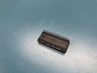
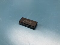
The mod requires eight stacks of two 128kx8 VRAM chips in SOJ package. 256kx8 will not work! Make sure to use 128kx8. I used Micron MT42C8128DJ-7 VRAM chips but others will work too, as long as the pinout of the new VRAM chips matches that of the chips used on your motherboard. The best way to confirm the pinout of your VRAM chips is to check the datasheet. The wiring for the stacking is to parallel all of the pins of the two stacked chips except as follows: All no-connect pins as well as the QSF pin of the top VRAM chip are to be cut off of the top chip and not paralleled with the bottom. The RAS and SE pins of the top chip in the stack should be separated from the bottom chip and bent upward so that jumper wire can be attached to them later.

Running the mod wires
Solder the eight VRAM chip stacks to the 660AV board, ensuring that once soldered, there will be enough room to attach wires to the RAS and SE pins which have been separated from the top stacked chip. Notice how on the motherboard there are two VRAM banks, one to each side of the 'F245 chips. We are basically putting a second bank of VRAM chips on each side. That is to say that we are adding two additional VRAM banks, one to the left to the 'F245s and one to the right. Once the vram stacks are soldered, bus together the RAS and SE pins for each of the two new banks of four chips, as shown in the pictures. You should have four wires on top of the soldered chip stacks, two RAS and two SE wires. These four wires must be soldered to the CIVIC video chip. For the VRAM bank which is closer to the CIVIC chip, RAS goes to pin 75 and SE goes to pin 106 on the CIVIC. For the further VRAM bank, RAS is CIVIC pin 64 and SE is pin 66. Notice how in the pictures of my 660AV motherboard, the CIVIC pins 75, 106, 64, and 66 are actually wired up to some series resistors placed around the chip. I connected my mod wires to the corresponding resistors rather than directly to the chip. Easier and the (series termination) resistors oughta be inline anyway. Make sure that the modwires are laying flat against the board, not standing up, and make the wires as short as possible.
 
Last edited:
  • Like
Reactions: -SE40- and iPhil64

Trash80toG4

Active Tinkerer
Apr 1, 2022
910
260
63
Bermuda Triangle, NC USA
Definitely, sick indeed! :p

I've been looking at doing similar things with Macs hobbled by undersized banks of onboard RAM for years. I wonder if the approach I've been pursuing would work for you?

Instead of stacking Chips, remove them and build a "VRAM SIMM Expander" for the single VRAM slot that will service two SIMMs. One is addressed as usual, the second would be on the shared bus, but jumpered to CAS/RAS on the vacated pads of the stock VRAM ICs with the balance jumpered to the unimplemented lines on the controller as you have done.

Pet projects of mine are IIsi, Q605 and Q630. IIsi is a 30pin PITA, but I've had that one worked out for the longest. Haven't been able to find my Q630 board so I can't use the 72pin SIMM expanders I have on hand.

Q605 is too low in profile to use same expanders I have on hand. :rolleyes: So I need to finalize my notion for a "reverse slope" low profile 72pin SIMM expander. Same deal, desolder the DRAM ICs of Bank A and jumper their CAS/RAS lines to expander slot two and jumper the remainder to the memory controller's unimplemented lines.

Such was done somewhere out on the web to a Q605 in the early days of 'fritter to achieve max controller supported RAM loadout. It worked, but was a horrible thing to behold and a kluge so nasty that dr. bob dubbed it the "Evil RAS Line Hack."

Is this making any sense to you? I'm tired.

IOW: instead of doing the agonizing, amazing, beautiful job of IC stacking that Garret has done in your 660AV, you'd just desolder the friggin' things. Then install the new contraption in the VRAM SIMM Slot and whale away with soldering iron connecting jumper wires from ready made locations on the expander to requisite pads on the board and legs of the controller.

The pair of VRAM SIMMs can be removed, but the expander with its two slots servicing all four banks remains forever in place.
 
Last edited: