This is the video that inspired me to follow in his track (Adrian's Digital Basement) and install a RGBtoHDMI pi zero + hat + buffer board to first my Macintosh Classic 1, then to my Mac Plus and eventually to a SE/30 in an upcoming update to this thread.
Project page to RGBtoHDMI: https://github.com/hoglet67/RGBtoHDMI
Quick link to my full Mac Classic 1 RGBtoHDMI configurations (on the device): https://tinkerdifferent.com/threads...installed-on-classic-plus-etc.2475/post-24640
Quick link to my full Mac Plus RGBtoHDMI configurations (on the device): https://tinkerdifferent.com/threads...installed-on-classic-plus-etc.2475/post-24641
Quick link to my SE/30 RGBtoHDMI configurations (on the device): https://tinkerdifferent.com/threads...installed-on-classic-plus-etc.2475/post-25236
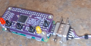
Specific board (hat board to the pi zero) I got to make sure I didn't gamble on something that strayed too far from what Adrian did:
I got the deprecated RGB 6/8 bit board here: https://github.com/hoglet67/RGBtoHDMI/wiki/Bill-of-Materials-(6-and-8-Bit-Boards) and had it made either with PCBWay or JLCPCB, I forgot which.
I also got the PC TTL buffer extender board, very important since it has diode chips to prevent the signals from returning to your mac:

 github.com
For the CPLD chip that's used by the hat board, they were available on mouser or digikey back then when I sourced my material, no idea if it's still easy to get. Good luck!

When you finalize the assembly, you'll need a small HDMI to regular HDMI converter and for the actual link to the wires that come out of my compact macs, I used a DB-9 (aka DA-9) connector, the same used for CGA / EGA PC monitors. You're just using 4 pins out of it. I used the great documentation in the above github page.

(older version where I had stripped soft wire ends that weren't very solid in the DA-9 connector pins)

You can find 3d printable cases out there, here's one I found quickly and seems to be available in March 2023:
 www.printables.com
Getting a Raspberry Pi in 2023 little offshoot guide:
-=-=-=-=-=-
For sourcing a pi zero, anything that's not a pico or pico W (rp2040) is hard to get, but NOT impossible. I was able to buy one in early 2022 and then the severe raspberry pi drought occured worldwide. It *IS* possible to buy some in 2023 as they are coming back in waves that sell out quickly with stores attempting to mitigate scalper activity. Here's the method:
1) you sit down with https://rpilocator.com/ opened on weekdays, properly set up to your preferences
2) you made accounts in advance in the stores you aim to buy from (ie Adafruit, PiShop, Sparkfun, etc)
3) you ACTIVATED 2FA capability in those websites as well and are ready to stay logged in for the week day dropdowns (read below)
4) you prepared IN ADVANCE a wishlist that you can add to your cart in 1 click (if supported, that's how I got a pi zero from adafruit US)
5) around 9-10 AM EST, some stores release 100 units oftentimes during some days of the week. There's no cemented pattern, you have to check it out many times during the course of several days to get a feeling. You can follow @rpilocator on Twitter or @[email protected] on Mastodon to understand those pattern, they post about drops as soon as detected.
-=-=-=-=-=-
The RGBtoHDMI in 1-bit mode uses 4 wires (hsync, GND, vsync and signal) and here's where I soldered my wires on my Mac Classic 1, on the analog board in cramped spaces near the microphone:

(view from inside the connectors, ie where the wires connect inside the cable.)
white to pin 4 = green 1 = "signal"
gray to pin 8 = h sync
violet to pin 9 = v sync
black to pin 1 = ground)

(revised "version" where I soldered male dupont ends for added robustness)
(as shown here, those 4 wires are soldered to the pin sides of a male DB9 connector, which itself is plugged into a female DB9 connector soldered on the RGBtoHDMI buffer TTL board)
Next up is where I soldered my wires inside my Mac Classic 1 - it's awkwardly on the analog board near the speaker. In hindsight, don't do this, use the same shove-inside the connector between analog and logic on the logic side. I did it this difficult way just to exactly reproduce Adrian's video back then while I was unsure of many steps.

Here's my configuration txt file for it
Here's what I did for my Mac Plus, shoving exposed Dupont wires into the J connector (logic board side) for the cable that links the analog board to the logic board. They hold real solidly by friction and from being squeezed in. I'm not afraid they'll suddenly come out and short something.

Here's a better view of the cable sockets I used for the Mac Plus:

I did a YouTube shorts on it:
and here's my configuation file for it:
One day, I'll do my SE/30 as well, since I use it often for making MIDI stuff, it'd be great to have this very useful insurance against failing CRTs for the long run.
Gear I use to capture video:
I used the cheap HDMI capture usb stick that gives me a plenty good 1920x1080 @ 30 fps:
ideally, I could use 60 fps but then it started to become expensive and it's not that needed.
Here's a video where I explain how to connect it to a Mac SE/30:
Example image captures (click to see in full view without resizing dithering that ruins some of the patterns)


Project page to RGBtoHDMI: https://github.com/hoglet67/RGBtoHDMI
Quick link to my full Mac Classic 1 RGBtoHDMI configurations (on the device): https://tinkerdifferent.com/threads...installed-on-classic-plus-etc.2475/post-24640
Quick link to my full Mac Plus RGBtoHDMI configurations (on the device): https://tinkerdifferent.com/threads...installed-on-classic-plus-etc.2475/post-24641
Quick link to my SE/30 RGBtoHDMI configurations (on the device): https://tinkerdifferent.com/threads...installed-on-classic-plus-etc.2475/post-25236
Specific board (hat board to the pi zero) I got to make sure I didn't gamble on something that strayed too far from what Adrian did:
I got the deprecated RGB 6/8 bit board here: https://github.com/hoglet67/RGBtoHDMI/wiki/Bill-of-Materials-(6-and-8-Bit-Boards) and had it made either with PCBWay or JLCPCB, I forgot which.
I also got the PC TTL buffer extender board, very important since it has diode chips to prevent the signals from returning to your mac:
Bill of Materials (TTL Buffer Boards)
Bare-metal Raspberry Pi project that provides pixel-perfect sampling of Retro Computer RGB/YUV video and conversion to HDMI - hoglet67/RGBtoHDMI
github.com
For the CPLD chip that's used by the hat board, they were available on mouser or digikey back then when I sourced my material, no idea if it's still easy to get. Good luck!
When you finalize the assembly, you'll need a small HDMI to regular HDMI converter and for the actual link to the wires that come out of my compact macs, I used a DB-9 (aka DA-9) connector, the same used for CGA / EGA PC monitors. You're just using 4 pins out of it. I used the great documentation in the above github page.
(older version where I had stripped soft wire ends that weren't very solid in the DA-9 connector pins)
You can find 3d printable cases out there, here's one I found quickly and seems to be available in March 2023:
Printables
www.printables.com
Getting a Raspberry Pi in 2023 little offshoot guide:
-=-=-=-=-=-
For sourcing a pi zero, anything that's not a pico or pico W (rp2040) is hard to get, but NOT impossible. I was able to buy one in early 2022 and then the severe raspberry pi drought occured worldwide. It *IS* possible to buy some in 2023 as they are coming back in waves that sell out quickly with stores attempting to mitigate scalper activity. Here's the method:
1) you sit down with https://rpilocator.com/ opened on weekdays, properly set up to your preferences
2) you made accounts in advance in the stores you aim to buy from (ie Adafruit, PiShop, Sparkfun, etc)
3) you ACTIVATED 2FA capability in those websites as well and are ready to stay logged in for the week day dropdowns (read below)
4) you prepared IN ADVANCE a wishlist that you can add to your cart in 1 click (if supported, that's how I got a pi zero from adafruit US)
5) around 9-10 AM EST, some stores release 100 units oftentimes during some days of the week. There's no cemented pattern, you have to check it out many times during the course of several days to get a feeling. You can follow @rpilocator on Twitter or @[email protected] on Mastodon to understand those pattern, they post about drops as soon as detected.
-=-=-=-=-=-
The RGBtoHDMI in 1-bit mode uses 4 wires (hsync, GND, vsync and signal) and here's where I soldered my wires on my Mac Classic 1, on the analog board in cramped spaces near the microphone:
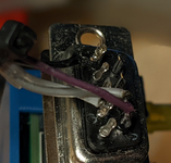
(view from inside the connectors, ie where the wires connect inside the cable.)
white to pin 4 = green 1 = "signal"
gray to pin 8 = h sync
violet to pin 9 = v sync
black to pin 1 = ground)
(revised "version" where I soldered male dupont ends for added robustness)
(as shown here, those 4 wires are soldered to the pin sides of a male DB9 connector, which itself is plugged into a female DB9 connector soldered on the RGBtoHDMI buffer TTL board)
Next up is where I soldered my wires inside my Mac Classic 1 - it's awkwardly on the analog board near the speaker. In hindsight, don't do this, use the same shove-inside the connector between analog and logic on the logic side. I did it this difficult way just to exactly reproduce Adrian's video back then while I was unsure of many steps.
Here's my configuration txt file for it
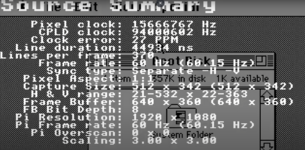
sampling=0,0,0,0,0,0,0,0,0,5,0,0,0,0,0,0,7,0,0,100,255,100,255,100,255,255,255
geometry=172,22,512,342,512,342,2,2,0,1,15667200,704,5000,370,1,0,0
Here's what I did for my Mac Plus, shoving exposed Dupont wires into the J connector (logic board side) for the cable that links the analog board to the logic board. They hold real solidly by friction and from being squeezed in. I'm not afraid they'll suddenly come out and short something.
Here's a better view of the cable sockets I used for the Mac Plus:
I did a YouTube shorts on it:
and here's my configuation file for it:
sampling=4,4,4,4,4,4,4,0,1,0,1,0,0,0,0,0,0,1,0,0,100,256,100,256,100,256,0,256
geometry=168,6,512,342,512,342,2,2,0,0,15667200,704,5000,370,1,0,0
palette=Mono_(2_level)
output_colour=1
output_invert=2
scanline_level=0
font_size=0
num_buffers=1
One day, I'll do my SE/30 as well, since I use it often for making MIDI stuff, it'd be great to have this very useful insurance against failing CRTs for the long run.
Gear I use to capture video:
I used the cheap HDMI capture usb stick that gives me a plenty good 1920x1080 @ 30 fps:
ideally, I could use 60 fps but then it started to become expensive and it's not that needed.
Here's a video where I explain how to connect it to a Mac SE/30:
Example image captures (click to see in full view without resizing dithering that ruins some of the patterns)
Attachments

Last edited: