PowerBook 165 replacement display ribbon cable

gfuller

New Tinkerer
I'm frustrated. 😤

Finally have everything to bring my PowerBook 165 back to life: Recapped LCD and inverter board, new power supply, J-B Welded hinge screw posts on the lid (plus two spare 3D-printed post assemblies, just in case.) I decided to spend this morning trying to put it all back together, despite another issue I ran into which I'll discuss a tad later.

The flat-flex LCD ribbon cable was being a major pain while attempting to reassemble the machine. I finally got it connected and adhered to the backside of the LCD assembly, but the ribbon cable kept flexing while attempting to fasten the screws on the LCD. (Didn't help my screwdriver bit kept falling out.) While connecting the inverter cabling connectors, somehow my fear came true — the ribbon cable broke right in half. I was trying to be gentle to avoid from that.

Does anyone here have a replacement ribbon cable, or is there anywhere you can purchase a replacement? What is the best way to replace it, since it seemed to keep twisting and had a lot of tension earlier?
IMG_6713.jpg
IMG_6715.jpg

On a slight tangent, I've had a couple other failures with this project. I'm trying to get a BlueSCSI configured for this machine.

Using Disk Jockey, I created a 500 MB volume on the microSD card. I'd like to install System 7.5.3 on the volume using Basilisk II (since I don't have any floppies to put the install images on), but Basilisk II won't open the .hda file from the setup GUI. Dragging it in, System 7.5.3 will prompt for the volume to be initialized. However, it won't let me initialize it because "the disk is locked." The image isn't locked. Is there something I'm missing?
Screenshot 2023-11-24 at 1.27.16 PM.png


I'm also trying to update the firmware on the BlueSCSI to enable WiFi modem emulation. I connected the BlueSCSI's Raspberry Pi using a cheap microUSB cable to my Mac mini, and tried dropping the UF2 file into the 'RPI-RP2' drive. (The cable appears to have the usual four connections on both ends, and I believe I may have used it to transfer data before.) It ejected but never automatically restarted, and the activity LED never blinked. Upon restart the activity LED very briefly blinks while connected to the Mac. I removed the SD card to see if I could find a 'log.txt' file on it. I never saw it. I did, however, find a 'err.txt' file on the first attempt, which I took a screenshot of. While subsequent attempts yielded the same failure, I never got another 'err.txt' file, but also never got a 'log.txt' file. Does this sound like an issue with my USB cable, or is there something else possibly happening here?
Screenshot 2023-11-23 at 11.18.04 PM.png

Hopefully I can get all this sorted out, because I contemplated just giving up after the cable snapped. As always, any help would be greatly appreciated.
 

gfuller

New Tinkerer
Got the replacement cable, and it seems to fit. Does the ferrite bead need to be wrapped around the new cable as well?

I'm now having issues getting the lid re-installed. The left hinge screw goes in perfectly fine, but the right screw won't even reach the boss in the lid.
 

Androda

TinkerDifferent Board Secretary 2023
Staff member
Sep 25, 2021
499
533
93
USA, Western
androda.work
Got the replacement cable, and it seems to fit. Does the ferrite bead need to be wrapped around the new cable as well?

I'm now having issues getting the lid re-installed. The left hinge screw goes in perfectly fine, but the right screw won't even reach the boss in the lid.
The ferrite bead mostly helps with interference. I would reinstall it, just wrap the outside closed with electrical tape.
 
  • Like
Reactions: RetroTechTom

gfuller

New Tinkerer
I reinstalled the ferrite bead.

I'm still unable to get that other hinge screw to go in, even after removing the other screw and trying to reposition the lid to see if I didn't have it properly installed. Every time I can get the left screw to go in just fine, but the right screw won't even reach the boss. Checked and it doesn't look like any J-B Weld is interfering with the fit or anything. Am I missing something?
tempImageVFatP2.png
tempImagejOJr1l.png
 

Androda

TinkerDifferent Board Secretary 2023
Staff member
Sep 25, 2021
499
533
93
USA, Western
androda.work
Did the screen cable replacement function? I'm not going to be any help on the hinge issue, mostly curious if the display works.
 

gfuller

New Tinkerer
Sorry for the delay. Work got in the way, giving me some time to take a break and think if there's anything obvious missing.

The ribbon cable does function, thankfully. I finally got the machine put somewhat back together for testing purposes.
IMG_6820.jpg


Not much has gone to plan with this restoration... and I'm thankful it works. Now I just have a few more things to battle with regarding this machine, including figuring out why I'm having such an issue with screws and that right hinge. The left screws go in just fine, but the right screws (as mentioned in previous posts) that originally came out refuse to reach the screw bosses and fasten down. I decided to try the gray screws meant for the outer holes (holding the bezel to the hinge/lid) and it reached just fine. I think I'm going to save buttoning things back up until a) I've figured out the screw issue or using the gray screws on the right hinge is OK (they're covered anyway, just worried I may not have two screws for the bezel); b) I can properly route the inverter wires (going to try seeing if I can push some of the slack inside the upper half to get the wires into the guides); and c) get the BlueSCSI going w/ WiFi (see original post, may start separate thread.)

I'll be so happy to finally get this machine all buttoned back up with the BlueSCSI installed.
 
  • Like
Reactions: Daniel Hansen

Androda

TinkerDifferent Board Secretary 2023
Staff member
Sep 25, 2021
499
533
93
USA, Western
androda.work
The ribbon cable does function, thankfully. I finally got the machine put somewhat back together for testing purposes.
I'm glad the ribbon cable works for you. Was your 165's original cable a "630-6271-A / 821-0104-A" like mine?

Now I just have a few more things to battle with regarding this machine, including figuring out why I'm having such an issue with screws and that right hinge. The left screws go in just fine, but the right screws (as mentioned in previous posts) that originally came out refuse to reach the screw bosses and fasten down. I decided to try the gray screws meant for the outer holes (holding the bezel to the hinge/lid) and it reached just fine.
This screw issue is really strange. Almost sounds like the mounts moved when you were re-gluing them.
 

gfuller

New Tinkerer
I'm glad the ribbon cable works for you. Was your 165's original cable a "630-6271-A / 821-0104-A" like mine?


This screw issue is really strange. Almost sounds like the mounts moved when you were re-gluing them.
I' ll have to take a look at the part number on the original ribbon cable, which I still have.

The screw issue still stumps me. I didn't cut/replace the screw posts/bosses... I just shored them up with J-B Weld. I don't see any J-B Weld or anything obvious that would interfere with the fit. If I can get the bezel to go on, I might just leave it how it is now even though it's not correct?

Since I see you're a BlueSCSI creator, any idea on why the new firmware might not be working? I've tried dropping the new uf2 file to the Raspberry Pi using my M1 Mac mini (running Sonoma) and my 2014 MacBook Air (running Mojave). Both failed. The file would act as if it was transferring to the drive, and the Raspberry Pi would reboot. However, I don't see a "log.txt" file on the SD card. I'd like to enable the WiFi functionality before dropping it into the PowerBook and buttoning everything back up.
 

Androda

TinkerDifferent Board Secretary 2023
Staff member
Sep 25, 2021
499
533
93
USA, Western
androda.work
Since I see you're a BlueSCSI creator, any idea on why the new firmware might not be working? I've tried dropping the new uf2 file to the Raspberry Pi using my M1 Mac mini (running Sonoma) and my 2014 MacBook Air (running Mojave). Both failed. The file would act as if it was transferring to the drive, and the Raspberry Pi would reboot.
After firmware has been flashed to the Pico stick, you should see a "blink code" from the green LED on the Pico. If it blinks once, that means it has read the SD card and is ready for use. Anything other than one blink is an error code, and those can be found here.

You may need to remove USB power and re-apply for the Pico to fully "reboot" and start running the firmware.
 

gfuller

New Tinkerer
After firmware has been flashed to the Pico stick, you should see a "blink code" from the green LED on the Pico. If it blinks once, that means it has read the SD card and is ready for use. Anything other than one blink is an error code, and those can be found here.

You may need to remove USB power and re-apply for the Pico to fully "reboot" and start running the firmware.
I reached out to Eric and he suggested removing the "HD0.rom" file from the SD card. I did that, plopped the .uf2 file onto the Pico, and checked the SD card. That seems to have worked, since I now see a "log.txt" file on the SD card. (Before, there was no "log.txt" file at all.)
Post a photo of the hinge mount from a front-on perspective where we can see down the hole. Sounds like you messed the alignment up when repairing it.
I've been under the weather lately, so I haven't had a chance to get a photo of the hole. I didn't replace the posts (just reinforced the original ones), so I'm not sure what would mess up the alignment. Maybe there's something odd going on.
 

gfuller

New Tinkerer
I'm glad the ribbon cable works for you. Was your 165's original cable a "630-6271-A / 821-0104-A" like mine?
The original display cable was indeed a 630-6271 Rev. A/821-0104 Rev. ? part. (The second revision letter was covered up by a blue sticker, but I believe it to also be a revision A.)

Post a photo of the hinge mount from a front-on perspective where we can see down the hole. Sounds like you messed the alignment up when repairing it.
Here it is. I actually had a somewhat fun surprise: After removing the long gray screw, I tried the metal screw (the one that's supposed to go there) and somehow it fit right in with some slight pressure from behind. Unfortunately, it "snapped" out after I tried to close the lid — with a piece of the J-B Weld. I tried putting it back in, but same issue as before — wouldn't fit. Put the gray screw back in, removed it, and put the metal screw in and it fit as before with some slight pressure from behind. It "snapped" out again after I tried to adjust the screen while using the machine.

I tried putting the bezel on and it wouldn't fit. It seemed like there was a gap on the bottom right corner (surprise, surprise) and the bezel screw wouldn't reach. 🤬 I have no idea what might be happening here to interfere with the fit unless it's the J-B Weld or perhaps the inverter wires? Speaking of which, I wonder if I have all the cables routed correctly. I tried to run the inverter wires to the right of the hinge, above it and around.

Still have the gray screw holding the lid to the hinge for the time being. Back to the drawing board on the lid/hinge/bezel issue, but at least the machine itself is functional. Hopefully I can get that issue figured out soon, along with additional software installed on my BlueSCSI, and get this thing buttoned back up completely. Also need to have the battery rebuilt with new cells.

Anyways, here's the photo of the hole and how the cables are routed.
IMG_6868.jpg


How the cables are routed. I removed the inverter board to pull the wires down into the cable, reducing the slack up above so it would tuck neat(er) into the display housing. Tried to do my best at running it up to the right, up and around the hinge.
IMG_6878.jpg


While trying to close the lid with the screws installed, I noticed the rear part of the lid where the right hinge attaches kept "bowing out," before the screw "snapped" out of the hole. Thankfully I haven't lost the screw, although I was close one time and a couple other times I had to remove the inverter board as it fell down inside the machine. Having little hand coordination sucks.
IMG_6884.jpg

The "snapping" of the screw kept concerning me, so I removed the LCD assembly (again) and inspected the screw posts to make sure no damage was done. It seems like parts of the J-B Weld chipped away, but the post itself is still intact thankfully. I still wonder if my liberal J-B Weld usage is causing all of these problems, but I just don't see how it interferes. And the left side seems to be fine, and it isn't much better.
IMG_6887.jpg


Although the frustration continues, I think I can finally see some light at the end of the tunnel. I have a feeling it's going to be something simple, like the J-B Weld, and I'll end up looking like an idiot in the end. Wouldn't be the first — or last — time working on computers have made me feel like the dumbest idiot in the world. 😆
 

Androda

TinkerDifferent Board Secretary 2023
Staff member
Sep 25, 2021
499
533
93
USA, Western
androda.work
I finally got around to writing a blog post about the progress so far... https://personal.garrettfuller.org/...intosh-powerbook-165-restoration-woes-part-1/

I will get more photos. I wonder if I could use a rotary tool (which I'd need to order) to remove some of the J-B Weld fairly easily without damaging the post/standoffs?
Replying to a question from your blog post here:

---------------------
First, I noticed the BlueSCSI has fewer pins than the old hard drive and the connector. I want to figure out the pin-out, or how to properly install the BlueSCSI in the connector, before I accidentally fry something or kill the BlueSCSI.
---------------------

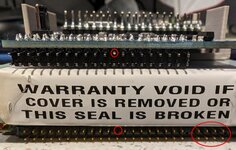
PowerBook BlueSCSI does have fewer pins than the original drive. This is because the original drive uses an extra segment of pins for SCSI Disk Mode to control which SCSI ID the PowerBook appears to be. BlueSCSI uses image file naming to determine SCSI ID as per the documentation.

Please notice that on the connector of your PowerBook BlueSCSI there is a silkscreen "X" and a pin missing (on 2023_10a revision the pin is circled). If you compare the connector against the original SCSI drive, a pin is missing there as well. If you line up the SCSI cable the same way it does for the original drive, then BlueSCSI will work fine.

See the attached picture for circled missing pins on BlueSCSI and an original PB SCSI drive, and those extra pins on the right are circled for SCSI Disk Mode to control the SCSI ID.
 

Attachments

  • PB_SCSI_PINS.jpg
    PB_SCSI_PINS.jpg
    230.6 KB · Views: 49
  • Like
Reactions: gfuller

gfuller

New Tinkerer
Replying to a question from your blog post here:

---------------------
First, I noticed the BlueSCSI has fewer pins than the old hard drive and the connector. I want to figure out the pin-out, or how to properly install the BlueSCSI in the connector, before I accidentally fry something or kill the BlueSCSI.
---------------------

PowerBook BlueSCSI does have fewer pins than the original drive. This is because the original drive uses an extra segment of pins for SCSI Disk Mode to control which SCSI ID the PowerBook appears to be. BlueSCSI uses image file naming to determine SCSI ID as per the documentation.

Please notice that on the connector of your PowerBook BlueSCSI there is a silkscreen "X" and a pin missing (on 2023_10a revision the pin is circled). If you compare the connector against the original SCSI drive, a pin is missing there as well. If you line up the SCSI cable the same way it does for the original drive, then BlueSCSI will work fine.

See the attached picture for circled missing pins on BlueSCSI and an original PB SCSI drive, and those extra pins on the right are circled for SCSI Disk Mode to control the SCSI ID.
I indeed noticed the X and missing pin, but didn’t think to look at the socket on the original drive. I‘ll give it another go tomorrow. Last thing I wanted to do is inadvertently fry the BlueSCSI or anything else.

I don’t have any kapton tape handy. Could I apply some scotch or electrical tape over the pins to prevent the Raspberry Pi pins from touching the drive bracket?

Also, what size screws for the 3D-printed bracket?

Machine still running fine. Now just trying to figure out what to do with the broken standoff. I wonder if I could easily remove the logic and daughter boards together to avoid needing to separate them. Then there’s still the lid problem.
 

Androda

TinkerDifferent Board Secretary 2023
Staff member
Sep 25, 2021
499
533
93
USA, Western
androda.work
I don’t have any kapton tape handy. Could I apply some scotch or electrical tape over the pins to prevent the Raspberry Pi pins from touching the drive bracket?
The PowerBook 1x0 series (other than original 100) uses a friction fit system for the SCSI drive. That's why the bracket has tall side walls - it's held down by the metal bracket and a peg which extends from the bottom case through one of the drive mount holes. If the friction fit seems too loose, double-sided tape can be installed under the bracket to help hold it in place. And of course the bracket seems to vary in size per machine. Tape on the bottom is probably a good idea.

Electrical tape would probably be safer for electrical insulation. I would recommend installing the electrical tape onto the underside of the metal bracket instead of applying to the BlueSCSI header pins. This is because adhesives break down over time and often become conductive, which could lead to strange faults. If the adhesive is only touching the underside of that big metal hard-drive bracket there's less to worry about.

Also, what size screws for the 3D-printed bracket?
M3 x 4mm

Machine still running fine. Now just trying to figure out what to do with the broken standoff. I wonder if I could easily remove the logic and daughter boards together to avoid needing to separate them. Then there’s still the lid problem.
I believe the motherboard and daughterboard can be removed without separating them. You just have to be careful about getting all of the cables removed first.
 

gfuller

New Tinkerer
It might be a bad/temporary solution, but I cut a piece of paper to size and taped it to the bracket to insulate everything from the drive bracket.

With that said, I got the BlueSCSI installed after realizing my dumb oversight on the pins. Machine fired right up into Mac OS 7.5.3. Even with 7.5.3 and only 4 MB of RAM, this machine still seems to fly in comparison to my Classic or even SuperSE. While I only installed a couple files and programs on the BlueSCSI (the rest to be installed later, after all other issues have been buttoned up; also need to recreate that ROM file in Disk Jockey), I'm happy to see that it finally works as it should.

Today another screw standoff post for that drive bracket broke... one of the two near the logic board on the opposite side of the floppy drive, with the other not in much better shape. When I initially removed the screws, they were torqued down pretty tight. I'm unsure if this machine has ever been serviced, as the IBM drive looks original. Then there's the hinge issue still.

What is the best, most "fool-proof" (given that everything else in this project hasn't gone to plan, mostly probably my fault) way to "restore" those standoffs? One is already pretty much gone, the other snapped today, and two others are very loose and feel like they could break soon too. I'm guessing I could use the J-B Weld on the ones that are still intact, but any advice for the two that have already broke?

Another random question about this project: Any "affordable" way to upgrade this machine's RAM? I see it only has the stock 4 MB PSRAM installed, but can be expanded to 14 MB. The original owner used some "virtual RAM" to bring it up to 8 MB, but I know that sacrifices performance and can affect storage reliability (even with modern solid-state and flash drives).
598E0591-12F9-4DC1-B5A7-A5EF1A60003F.JPG