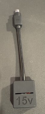
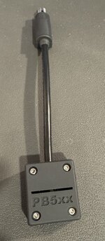
PowerBook 1xx USB-C PD Adapter

PotatoFi

Active Tinkerer
Oct 18, 2021
175
367
63
I finally smuggled a PowerBook 145B and 160 to Finland where I've lived for a year, which means I'm finally able to play with old Macs again! I opted to not bring the power adapter with me, since they're pretty heavy and would require a plug adapter to work. Instead, I hacked together a USB-C PD to PowerBook adapter!

IMG_0386.JPG


The implementation is super simple: It's just a 15V USB-C Power Delivery trigger board, a variable step-down converter, and a pigtail in a 3D-printed case. Here's the complete bill of materials:
Annoyingly, with these links you can't build just one, so consider doing a group buy with some friends or selling the extras (I'd send some out but shipping from Finland is expensive). You can optionally purchase a USB-C power meter to see what your adapter is outputting.

IMG_0399.jpeg


I also tested nearly all of my USB-C PD power adapters (and battery):
  • Apple 35W Dual USB-C Adapter, Model A2571
    • Ships with M2 and M3 13" MacBook Air
    • Outputs 15V at 2.33A
  • Apple 30W USB-C Power Adapter, Model A2164
    • Ships with M2 13" MacBook Air
    • Outputs 15V at 2.0A
  • Apple 20W Adapter, Model A2935
    • Ships with the 10th generation standard iPad
    • Outputs max 9V, 2.22A
    • Despite not supporting 12V, seems to work great with the PowerBook 160
    • The Step Down Converter seems to maintain an even 7.5V, even though the input voltage is lower
  • Ventev Wall Charger 585920
    • Outputs 15V at 3.0A
  • Anker PowerCore 20100 Nintendo Switch Edition
    • Outputs 15V at 2.0A
Any USB-C adapter that supports 15V or 9V with at least 2A should work. The trigger board will request 15V, and if not available, will step down to the next available voltage. I would recommend confirming the output voltage before connecting to your PowerBook, and then re-resting after connecting the PowerBook to be sure that everything is correct.

Here it is with my Apple 20W adapter that came with a 10th-gen iPad. This adapter outputs a max of 9V, so when the trigger board asks for 15V, the adapter simply outputs the highest voltage that if offers. Although I tuned the step-down board for 15V input, the output is still 7.55V.

My PowerBook 160 has been powered with this adapter for most of the weekend. With the adapter on it's side (so both sides of vents are exposed) I saw a max temperature of 38°C / 100°F on the exterior of the case. With the 9V adapter I see about 1.3A, and with a 15V adapter I see about 0.8A. Note that I don't have a battery in this machine, so I'm not sure what kind of load charging a battery would add.

IMG_0384.jpeg


To assemble it:
  1. Solder together the boards
  2. Place them in the enclosure
  3. Connect a power supply
  4. Measure the output voltage, and adjust the potentiometer until the output is approximately 7.5 volts
  5. Connect it to your PowerBook, and boot it up
  6. Now that the adapter is under a normal load, carefully fine-tune the voltage to 7.5 with 1/16th turns
  7. Shut down the PowerBook, remove power, and install the top half of the case

IMG_0385.jpeg


Of course, the printed case, BOM, and instructions are all available on Printables. There's also the Fusion 360 file, so if your pigtail wire is a different diameter than mine (6 mm), there's a single variable you can adjust. I've also included a PrusaSlicer file with the paint-on supports all done, so you can quickly slice and print it.

Special thanks to @MacintoshLibrarian, who I think suggested the step-down board when I floated this idea about 1.5 years ago.

IMG_0400.jpeg


As always, carefully check your voltages before connecting this to your PowerBook!
 
Last edited:

wottle

Active Tinkerer
Oct 30, 2021
526
274
63
47
Fort Mill, SC
This is awesome. I've been exploring options for my vintage laptops and basically came to a similar solution to yours. I originally built a variable output device thinking one device for everything, but now I like the idea of USB-C with step-down / step up converters dedicated for each of the 3 main voltages for vintage Macs.

There's 7.5v for the Portable / 1xx series (although the pickiness of the Portable probably warrants just keeping a dedicated 7.5v 1.5A charger).
16v for the 5xx series (I'm hoping maybe the straight 15v from the usb-C PD trigger board will suffice).
And finally, 24v with various adapters for the PB5300/190/1400/3400/Duo/G3, iBook G3/G4 range.

I tested an iBook G4 with 20v straight from the USB-PD trigger and it SEEMED to work fine, but other convinced me it would be best to get a solution with 24v.

This would in theory allow me to have a big USB-C battery, 3 cables (7.5,15v,24v) and a handful of adapters. I might even look into forcing a different connector for the different adapters to prevent me being silly and plugging a 5xx adapter into my 24v cable.

Anyway, I appreciate your efforts here and your 3d modelling skills are much better than mine. I love the size of your enclosure and the fact it's passively cooled.
 
  • Like
Reactions: PotatoFi

wottle

Active Tinkerer
Oct 30, 2021
526
274
63
47
Fort Mill, SC
OK, I put together my own versions of these. One using the buck converter you specified, and two using this boost converter to get 16v and 24v versions: https://www.amazon.com/dp/B07BNHR4HW?ref=ppx_yo2ov_dt_b_fed_asin_title&th=1
Screenshot 2024-09-20 at 2.48.37 PM.png


I chose it because it matched the dimensions of the buck converter you used in your design. Mine came with a bit of extra PCB still attached to the end of each board that I had to snap off... But once I did, they fit the same. In fact, it almost looks the same as the original buck converter, but flipped around.

I probably could have managed to use the straight 15v output of the USB-C boards you used, but since I ordered a 10 pack of the boost converters, I figured I may as well try to get as close to the appropriate voltage for each type of connector. My plan is to get a broken PB5xx charger to harvest the connector from and directly wire it in.

In addition, I printed some labels but thought it would be nice to have the voltage printed on the case, so I messed around in Meshmixer and created both tops and bottoms with the voltage specification embossed in the surface. I'm printing now to see how they turn out. I'll post the STLs later if anyone is interested.
 

PotatoFi

Active Tinkerer
Oct 18, 2021
175
367
63
Nice work, @wottle! I considered putting the output voltage on mine, too. Heads up, PrusaSlicer has built-in text embossing too, so that could be a quick way to add voltage labels.

I've considered adding variables for the width, height, and length of the buck/boost boards, in addition to the variable for the output cable diameter. This could enable better compatibility with various buck/boost boards when people are shopping. The downside is that everyone would have to fire up Fusion 360, edit the variables, and then output the models. I sure with there was a "Fusion 360 Lite" to streamline the process.

If anyone is interested in that, let me know and I can look into those adjustments.

I also feel like the board fit is super tight; I think I can make a spring-loaded section of the part (like my SD to 2.5" IDE hard drive caddy) to make board installation easier.
 
  • Love
Reactions: wottle

wottle

Active Tinkerer
Oct 30, 2021
526
274
63
47
Fort Mill, SC
Appreciate it. I may need to look into PrusaSlicer (I use Cura just because it's what I learned on and I have my printer settings the way I like them). I used Stamping in MeshMixer to add the voltages, but I'm guessing PrusaSlicer would be a much easier, cleaner process. Here's the finished product, along with my current set of 24v adapters.

IMG_2246.jpeg
IMG_2244.jpeg


I think the current model is perfect given the boost / buck converters appear to be readily available in the sizes you have setup. One of my 5.5mm cables was a bit small so I just wrapped it in electrical tape to give a secure fit. I've not used Fusion360 - would the free version be enough to do the modifications needed to customize the model?

As for the board tightness, I noticed this and wasn't sure if it was just my new 3d printer / new filament. I ended up scaling up by 100.5% and it worked well for me. A spring mechanism that provides a bit more room for differences in printers and materials would be amazing.

Again, thanks for building this out! It's going to be awesome storing all my laptop power supplies and ending up with just this cluster of USB-C based ones. I already have a magzafe USB-C cable, so I can pretty much handle any of my machines (except my Portable) with just these cables.

So maybe your idea of adding options for the board size would be helpful. I wonder if being able to throw a constant current buck-boost module (like this? https://electropeak.com/lm2596-2577) would allow for building one that would allow me to set the 7.5v/1.5A limiter that would allow it to be safely used with my Portable as well?

Update: I went a bit overboard with the text debossing in PrusaSlicer and added the machines that the charger can be used with on the underside:

IMG_2277.jpeg
IMG_2278.jpeg
 
Last edited:

wottle

Active Tinkerer
Oct 30, 2021
526
274
63
47
Fort Mill, SC
Minor update. I haven't used the adapters too extensively yet, but I did break two of my boost converters powering my PowerBook G4 (Al 12") for only about 5 minutes. I forgot this one actually has a battery that takes a charge, and I believe a combination of boosting the voltage from 15v to 24v, as well as increased current to both power the machine and charge the battery likely caused the boost converter to overheat. After failure, I tested and the boost convert's failure mode is to apparently just pass through the 15v input to the output. Also, after failing, the XL6009E1 chip got blazingly hot. So, not ideal

So I noticed that the USB-C trigger boards that I bought at 15v allow for you to choose 20v by creating a solder bridge. So I did that, added a new boost converter, and got to 24v output with 20v input. I assume that will be easier on the boost converter. So I ran a longer test and the converter, while getting pretty warm, was able to work for 15 minutes at 24v output and 1.75A (I believe the max for those machines original PSUs was 1.88A - 45W?). So I'm going to do some further testing later, but I think I'm also going to try to always uses these lightweight adapters with no batteries in the laptops. Or only charge the batteries, not while using.

The failure mode of the boost converter did have me thinking about a scenario where the buck converter fails. If it does, I'd be very worried about the 15v being sent through. So I may look to buy the 9v version of the USB-C trigger board. That will limit damage if it does "fail open". And for my 16v version, failing to 15v will likely be just fine. But just a word of caution for others that may be using with a voltage sensitive machine (I'm assuming the PB1xx series are, given how incredibly finicky the Portable was).

However, I love the form factor and am still hoping I can store all my old power bricks in the garage and use these, I will be very happy. Thanks again.
 
  • Like
Reactions: PotatoFi

wottle

Active Tinkerer
Oct 30, 2021
526
274
63
47
Fort Mill, SC
Update number 2. The new adapters that do smaller boosting of voltage seem to be working well. I'm using a 20v trigger board for the 24v and a 15v trigger board for my 16v adapter, both with boost converters.. Both ran for a good amount of time without failing / overheating. The 7.5v adapter still uses the 9v with a buck convert.

I was looking into ideas to make my IIc somewhat portable (USB-C power and an LCD that runs off the monitor port) and found this:
1730650324302.png


Available at https://8bitstuff.com/product/apple-iic-usb-c-power-adapter-with-volt-gauge/

(Note on 8bitstuff.com - be careful. Not sure if it was just me, but it defaulted to the UPS next day air option for shipping, which was $99!. Shipping is $15 for the cheapest, so I'll likely just build my own since I have the USB-C trigger boards, a great little adapter pattern, and the connectors to make an adapter for the Iic)

Very cool idea. Really like the voltage display - would be cool to incorporate into this design! Would give me confidence in the buck/boost converter doing its thing.

Eventually between this and PicoPSUs, I hope to have somewhat reliable long term power solutions for all my machines.
 

wottle

Active Tinkerer
Oct 30, 2021
526
274
63
47
Fort Mill, SC
AdaFruit sells premade USB-C to barrel jack cables. They’re only available in the standard USB-PD voltages, but they seems like a simple solution. Just chop off the barrel jack and wire the right connector for your retro device! (I plan to do that for my Apple //c)
That’s a good option for people that haven’t already bought the trigger boards. Less work than printing a box buying a trigger board.

Update: built and works very well. Since there was no buck/boost converter in the 3d printed case, I used hot glue to secure the usb trigger board on the one end and the cable on the other. But it powered my Iic just fine, along with the LCD that pulls 12v/composite from the monitor connector! In theory I could power it from a USB-C power brick. Not sure how long it would run, but I need to grab some floppies and give it a shot.

IMG_2704.jpeg
IMG_2705.jpeg


IMG_2706.jpeg


IMG_2707.jpeg
 
Last edited:

Opualuan

New Tinkerer
Oct 10, 2024
13
5
3
These seem small enough to build into the (empty) battery bay of a powerbook. Combine with a small usb-c battery pack… maybe a path back to portabllity?

At a minimum this would require disabling of the stock power input port on the powerbook for safety.
 
  • Like
Reactions: eric

wottle

Active Tinkerer
Oct 30, 2021
526
274
63
47
Fort Mill, SC
These seem small enough to build into the (empty) battery bay of a powerbook. Combine with a small usb-c battery pack… maybe a path back to portabllity?

At a minimum this would require disabling of the stock power input port on the powerbook for safety.
I think the challenge is that the internal battery contacts, I don’t believe, are simply able to supply voltage. I think there’s an expectation of the battery management doing things and communicating with the laptops. And, as you noted you’d have to disable the power input so you’re not feeding power the wrong way.

I don’t mind having a USB-C battery pack and a small adapter to power my laptop to gain the portability. If you built it into the battery bay and figured out the BMS, you might as well add some batteries and simply produce a battery pack.