Restoring my Final Grail Item - The Resurrection of a Lisa 2

warmech

Tinkerer
Oct 30, 2021
79
101
33
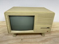
Going to try to keep this a cross-post with 68KMLA, but I've managed to acquire a Lisa 2 and will detail my repair endeavors here...

I was cruising Facebook marketplace a couple weekends ago and came across something I never thought I'd see an ad for on there: a Lisa 2. The asking price was reasonable-ish, but once I saw the description and photos of the battery area, my heart sank a bit. "Used to power on, but now no longer does..." accompanying the telltale blue-green hue of corrosive battery damage. I decided to ask about it and see where things went. No mouse or keyboard were included (bummer), but the seller was more than happy to send additional photos of the corrosion. I decided to post a price check thread on 68KMLA to solicit opinions about what in the heck something in this state may go for and got a handful of extremely helpful responses - the $500-1000 range seemed fair and on-point. I asked the gentleman if he would be willing to meet up for me to take a look at it in person, so we setup a time to meet in front of the police station down the road from him.

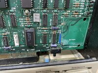
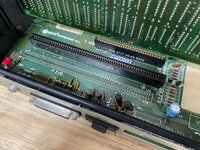
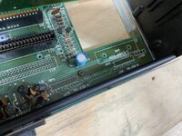
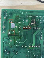
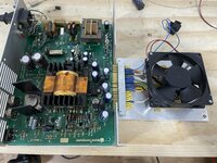
The next Wednesday afternoon rolls around and my wife and I head across town (more like three counties - welcome to DFW) to take a look. The guy was really, really nice and we struck up a conversation about the Lisa; it belonged to his great uncle (who bought it new, if I recall) and had sat in his house for the last few decades untouched. His great uncle came across it and gave it to him to sell for money for school, figuring it was probably worth something. The guy had already sold the mouse, keyboard, and Profile on their own on eBay and made decent money off of them - unfortunate for me, but I was genuinely glad he'd managed to get good money for them. He knew the Lisa would be difficult to ship (and was dead as a doornail) so he wanted to try to hand it off locally rather than take a chance on shipping. I took a look at the board and, sure enough, it'd been hit by the usual cause of death via battery leakage. Fortunately, it looks manageable and to have only hit replaceable components. The traces are a mess and will take extensive work to repair but the COP421 looks completely clean, so my fears of that thing taking a hit were relieved. By far, the most difficult thing to replace on this is going to be the card edge connector (more on that later). We talked for a few and I threw out a figure that we negotiated on and eventually came to an agreement: $600. With that, and after over a decade of waiting, I walked away with my very own Lisa. :)

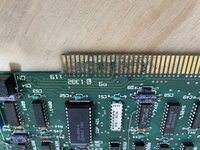
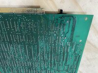
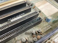
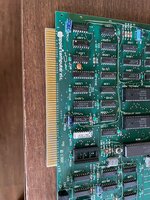
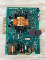
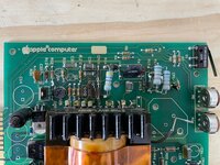
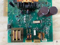
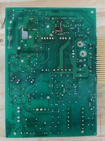
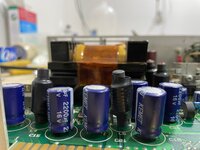
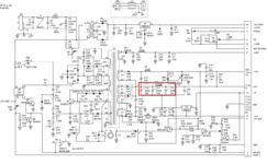
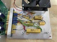
On to the state of this thing. The I/O card edge is going to need some work; thankfully, I know just the guy to re-pad it. It doesn't look like any of the connectors have completely gone, but a fiberglass pencil isn't gonna save it either. The card edge connector on the main board, however, will require replacement - its pins are absolutely ruined where there was corrosion (to the point of disintegration) and I have a replacement on the way. The resistor packs will need to be replaced and some traces cleaned up, but it otherwise looks okay. As for the I/O card itself... oof. It's gonna need some new ICs here and there (the 1488 and 1489 are absolutely toast) and a ton of traces repaired, but neither are beyond my skill or patience. The CPU and RAM cards look fine and dandy, so I'm not really worried about them. The PSU is... shrug? It had a blown fuse (which I have replaced), but I have yet to diagnose further. If the soft-power traces are toast, though, will it even power on? I have yet to attach power to it (nor do I have any intention to yet), but it no longer powers up according the the seller so we'll see if it was, in fact, just the fuse. I'll certainly make sure the transistors are tested and that there are no visible component failures, as well as replace the caps and deoxit the pots, but I need to read up on how to test the PSU. Any Lisa owners out there have any advice on how to proceed? Not just with the PSU, but with anything and everything. I'm no stranger to working on PCBs, but this is probably the only Lisa I'll ever come across and I'd rather like to not do any further damage to it.

I don't have a keyboard but, if I can get this thing to come back to life, I'm willing to drop the cash on one. Since a Mac mouse can be used, I really, really don't care to spend three-figures on a Lisa mouse. Wish me luck folks... it's gonna be a bumpy ride.
 

Attachments

  • IMG_3954.jpg
    IMG_3954.jpg
    851.9 KB · Views: 85
  • IMG_3956.jpg
    IMG_3956.jpg
    1.4 MB · Views: 91
  • IMG_3957.jpg
    IMG_3957.jpg
    973.1 KB · Views: 78
  • IMG_3958.jpg
    IMG_3958.jpg
    1.1 MB · Views: 83
  • IMG_3962.jpg
    IMG_3962.jpg
    1.1 MB · Views: 90

warmech

Tinkerer
Oct 30, 2021
79
101
33
Forgot to post this earlier and already have a couple of updates!

First, I have a keyboard on the way, so yay!

Second, I've had a chance to clean this thing up quite a bit. the I/O board pins are fine and a fiberglass brush did indeed take care of them, much to my surprise. There are some broken traces coming off of them, but none of the pins are lifted of the board which means I will not have to re-pad them. There was a decent amount of corrosion elsewhere though, and that has been largely mitigated. I've still got a bit to go, but traces have been taken down to copper where the corrosion was the worst and I've verified that most of the traces are still intact. Some are broken, though, and will require bodges; that's more than doable, though. I'm going to have to replace most of the ICs in the area around the batteries, but I have them on-hand and ready to go into sockets when the time comes. The COP421 has been sealed up in an anti-static case, so it's safe and sound for a later time, lol.

The motherboard was in better shape than I was anticipating. I've removed the large connector and cleaned either side of the board where it was. Thankfully, only three pads came off and they appear to be easily bodge-able to their respective destinations. The EMI filters were absolutely toast, though, along with the two serial ports - they are all being replaced. The EMI filters, for those who read this, are still available at Digi-Key, but boy oh boy are they expensive now ($6.24 apiece)! Also, for those curious, the motherboard screws on a Lisa 2 are #4-40, in case some of yours were as corroded and stripped out as mine were.

The PSU is the major stumbling block at the moment, more to come on that...
 

Attachments

  • IMG_4001.jpg
    IMG_4001.jpg
    653.6 KB · Views: 69
  • IMG_3998.jpg
    IMG_3998.jpg
    687.5 KB · Views: 74
  • IMG_3999.jpg
    IMG_3999.jpg
    540.3 KB · Views: 66
  • Like
Reactions: KingDingus

warmech

Tinkerer
Oct 30, 2021
79
101
33
As for the PSU, it makes the familiar chirping when attempting to power on the Lisa (the I/O board is removed for cleaning, but I wanted to verify the machine would even power on first), so I've been going over everything I can think to. Using the thread by @rdmark as a guide, the six main transistors all seem to check out fine; the only issue I can think of is that Q1 returns .462v when testing base to collector and .525v when testing base to emitter. I'm not familiar enough with transistor testing to know if those are within spec, whereas all the rest of the 3904s test in the .6v range and look completely fine. Outside of that, I've located what I think to be a short, but I'm a bit confused by it (mostly due to my not being very knowledgable about transformers). In the attached image, the four transformer pins all have continuity, which is slightly alarming to me as it means that all three pins boxed in red in the top-left also all have continuity. As those three pins go to CR17, I'm pretty sure that's no good, lol. As for the lower left-hand box, those four pins also have continuity between Q1's base pin and the trace to its left. Is this a sign of a short within the transformer? With the transformer removed these continuities go away, so I know it's local to the transformer. Any thoughts or suggestions? Additionally, I'll be recapping the PSU this evening as well; the caps are all 40-ish years old and I assume surely can't be in spec anymore.
 

Attachments

  • IMG_3995.jpg
    IMG_3995.jpg
    1.3 MB · Views: 57

rdmark

Moderator
Staff member
Oct 3, 2021
116
176
43
Thanks for documenting your own Lisa journey! It's interesting to contrast your experience with mine. Looking forward to seeing your progress moving forward.

As I'm sure you're aware, a blown fuse is never just a blown fuse, but a sign that something else is (or was) wrong in the circuit. I guess it could have been some kind of mains power surge that the PSU couldn't handle, but that possibility is fairly slim IMHO. Since it sounds like to attempted to power it on, I assume that you checked that the fuse didn't immediately blow again, right?

Once I've wrapped up work for the week I can have a look at the PSU I have on hand here to see if I can measure those same shorts. I'm not well versed enough in electronics to tell you for sure, but the transistors do seem to test ok there. Do you mind sharing a picture of the populated side of the PSU PCB? There are two major revisions of the Lisa PSU that I'm aware of, with quite different designs.
 

warmech

Tinkerer
Oct 30, 2021
79
101
33
Thanks for documenting your own Lisa journey! It's interesting to contrast your experience with mine. Looking forward to seeing your progress moving forward.

As I'm sure you're aware, a blown fuse is never just a blown fuse, but a sign that something else is (or was) wrong in the circuit. I guess it could have been some kind of mains power surge that the PSU couldn't handle, but that possibility is fairly slim IMHO. Since it sounds like to attempted to power it on, I assume that you checked that the fuse didn't immediately blow again, right?

Once I've wrapped up work for the week I can have a look at the PSU I have on hand here to see if I can measure those same shorts. I'm not well versed enough in electronics to tell you for sure, but the transistors do seem to test ok there. Do you mind sharing a picture of the populated side of the PSU PCB? There are two major revisions of the Lisa PSU that I'm aware of, with quite different designs.
Yeah, that was my worry - the fuse was just the iceberg for something else inside the PSU. Fortunately, it doesn't blow after being powered on now, though.

Thank you for taking a look at your PSU! I'll grab some pictures of mine in a moment after I finish inhaling lunch.
 

warmech

Tinkerer
Oct 30, 2021
79
101
33
Alrighty - PSU images attached!
 

Attachments

  • IMG_4002.jpg
    IMG_4002.jpg
    541.2 KB · Views: 67
  • IMG_4003.jpg
    IMG_4003.jpg
    504.1 KB · Views: 80
  • IMG_4004.jpg
    IMG_4004.jpg
    531.7 KB · Views: 82
  • IMG_4007.jpg
    IMG_4007.jpg
    437.9 KB · Views: 107
  • Like
Reactions: KingDingus

warmech

Tinkerer
Oct 30, 2021
79
101
33
Signs of life... sort of.

I recapped the PSU and checked the six main transistors. Mostly satisfied with the results, I checked everything for glaring issues, dropped the PSU back in its cage, and fired everything up... to hear the CRT coming to life and see the power indicator light on the front button light up! For about 5-10 seconds, after which everything died again and I could smell the familiar smell of dead caps. Sure enough, the fuse had blown again and caps C18 and C21 had very puffy tops (see below); oddly, C19 is part of the same section, but looks fine. I'm looking at the schematic for this section and it looks like they're part of the +5v section; they're seated in the correct polarity, so I'm a bit unsure what would cause that.

Back to the drawing board for the moment, I suppose. Anyone have any ideas on how to approach this, lol?

Edit: Been in touch with a fellow on Facebook who's walked me through building a PSU bench test rig. I'm having Carpal Tunnel surgery tomorrow (yay, finally getting feeling back in my right hand!) but Friday or Saturday I'll get it assembled and have an external means of testing the PSU. The good news is that the rest of the unit seems to be fine; I pulled some logic chips off the CPU board and they tested fine, so overvoltage protection looks like it did its job.
 

Attachments

  • IMG_4026.jpg
    IMG_4026.jpg
    287.5 KB · Views: 66
  • Screen Shot 2022-06-06 at 7.17.55 PM.png
    Screen Shot 2022-06-06 at 7.17.55 PM.png
    105.4 KB · Views: 69
Last edited:

warmech

Tinkerer
Oct 30, 2021
79
101
33
Okay, the results are in! I assembled a load tester (pics below) and got the following voltages before the fuse blew again:

+5v rail: +8v
+12v rail: +18v
+33v rail: +53v
-5v rail: -5v (one success, at least)
-12v rail: -18v
+5 standby: +5v (5.5, but, eh)

The same two caps puff up after a very short while and, while they still appear to be functional at the moment, will probably fail shortly. I must admit that I'm a bit confused as to where to look next; this is farther into PSU territory than I've ever waded before. :(

I suppose the biggest question on my mind at the moment is how potentially damaged could things in the Lisa be given these readings?
 

Attachments

  • IMG_4031.jpg
    IMG_4031.jpg
    1.1 MB · Views: 81
  • IMG_4032.jpg
    IMG_4032.jpg
    1.1 MB · Views: 76

warmech

Tinkerer
Oct 30, 2021
79
101
33
Interesting load tester! Can you please share your design?
Surely! I'll grab the project list from Mouser in a bit. The card edge connector was off of a Pac-Man arcade PCB filter board I had lying around, but they can be had for about $6 from Mouser as well (22/44 pin EDAC brand).
 
  • Like
Reactions: AndyDiags

rdmark

Moderator
Staff member
Oct 3, 2021
116
176
43
Okay, the results are in! I assembled a load tester (pics below) and got the following voltages before the fuse blew again:

+5v rail: +8v
+12v rail: +18v
+33v rail: +53v
-5v rail: -5v (one success, at least)
-12v rail: -18v
+5 standby: +5v (5.5, but, eh)

The same two caps puff up after a very short while and, while they still appear to be functional at the moment, will probably fail shortly. I must admit that I'm a bit confused as to where to look next; this is farther into PSU territory than I've ever waded before. :(

I suppose the biggest question on my mind at the moment is how potentially damaged could things in the Lisa be given these readings?
Holy overvoltage, Batman! Sorry if you mentioned this earlier, but did you try to tweak the potentiometer on R29? As I mentioned over at my post, that pot caused overvoltage which triggered the overvoltage protection instantly on my PSU. You may want to drench it in contact cleaner to make sure no oxidation is left inside, or potentially even replace it.

Another tip that I read in a thread somewhere on Lisalist, is that the optocoupler on U3 may go bad with age and cause voltage issues. It has an LED inside the package with wears out with heavy use. And supposedly (this is 2nd hand information) it is in charge of decoupling the hot and cold side of the PSU and a failure mode is that the voltage on the cold site get ramped up beyond spec. I preemptively replaced the one in my PSU with one from this eBay seller.

Anyhow, my apologies for the delay in responding here. Inbetween catching COVID-19, and then catching up with work after recovering from said infection kept me away from most leisure activities.
 

warmech

Tinkerer
Oct 30, 2021
79
101
33
Holy overvoltage, Batman! Sorry if you mentioned this earlier, but did you try to tweak the potentiometer on R29? As I mentioned over at my post, that pot caused overvoltage which triggered the overvoltage protection instantly on my PSU. You may want to drench it in contact cleaner to make sure no oxidation is left inside, or potentially even replace it.

Another tip that I read in a thread somewhere on Lisalist, is that the optocoupler on U3 may go bad with age and cause voltage issues. It has an LED inside the package with wears out with heavy use. And supposedly (this is 2nd hand information) it is in charge of decoupling the hot and cold side of the PSU and a failure mode is that the voltage on the cold site get ramped up beyond spec. I preemptively replaced the one in my PSU with one from this eBay seller.

Anyhow, my apologies for the delay in responding here. Inbetween catching COVID-19, and then catching up with work after recovering from said infection kept me away from most leisure activities.
Geez, dude - more than anything, glad to hear you're doing okay! R29 is functionally useless; I've replaced it with another pot with the same results - no adjustment to output voltage whatsoever. I'm combing through LisaList for info on U3; there's only one left on eBay, so I may go ahead and pick it up.

Edit: Just checking - that looks like a relay more than anything. There's an OEC in there too?
 
Last edited:

AndyDiags

Tinkerer
Dec 18, 2021
88
157
33
R29 is functionally useless; I've replaced it with another pot with the same results - no adjustment to output voltage whatsoever.
I think that's a really good clue! This means that the feedback is not working at all, so rdmark may be right on the nose! I've had two Mac Plus's where the optocoupler died, causing the voltage adjustment pot to not do anything and voltages to be off. That looks like a really rare part too!

What's really odd here is that you're getting an 8v reading instead of 5v, and the capacitors which are rated for 16v are blowing.
 

warmech

Tinkerer
Oct 30, 2021
79
101
33
This might be helpful for getting your Lisa going again...


-Jason
The heck? Are you the guy who designed these? If so, kudos! If not, thank you very much for pointing me in their direction! This is fantastic and serves as a good time to update with progress.

So, the PSU is sidelined for the moment. It's not dead dead, just "TV" dead (it'll probably be back). In the mean time, I'm working off of an ATX PSU that's using a voltage booster to get +33v that's been wired up to a fingerboard edge connector. Janky, yes, but functional. In all, though, this Lisa is showing signs of life. The attached videos show what happens with each of the RAM cards inserted individually. As you can see, one of them is enough to get a partial hardware test going, while the other is not too functional looking. This leads me to my current task (which is fitting considering the github link) - reverse engineering the RAM cards.

I've pulled every single component from one of the cards and scanned both sides of the PCB. I need to re-scan them on a slightly higher resolution scanner and with a small sheet of lexan or plexiglass sitting under them to account for the levers at the top of the PCB. Stupidly, I left my local copy place without paying close enough attention to the top edge of the PCB only to get home and realize that the PCB was slightly warped looking due to the levers propping up that edge and distorting the scan. Gonna try to do that at lunch tomorrow.

The major issue, as with the motherboard PCB in the above github link, is that the RAM cards are four layer boards. The good news is that the two inner layers appear to merely be ground planes, which I can probably work around. That should tell you how much of a pain in the butt it was to get everything off the PCB, lol. I'm going to try to get everything traced this weekend and have a friend check my work. If all goes well, I'll probably try to order a prototype in the next few weeks. Once that's done and verified working, I plan on moving on to removing everything from my I/O board and doing it next - thankfully, it's only a two layer board. Someone has reproduced them before, but I can't get ahold of them to order one (if they even have any left - their last update was from 2018). After that, I'm going to try to find a dead CPU PCB somewhere and get it reproduced as well. My goal by the end of this year is to have a complete set of gerber files that, if one were so inclined, would allow anyone to just build a Lisa 2 (the brains of one, anyway) from scratch.

We'll see how all that goes but, after looking at the work done on that github repo, I'm feeling a lot of drive to make this happen in the next several months.
 

Attachments

  • IMG_4065_480.mov
    2 MB · Views: 0
  • IMG_4066_480.mov
    2 MB · Views: 0

warmech

Tinkerer
Oct 30, 2021
79
101
33
Small preview of where things are headed; this is just a rough draft, so don't worry too much about some of the positioning and silkscreen issues.

More to come later this week; stay tuned...

Screen Shot 2022-07-18 at 1.07.56 AM.png
 
  • Like
Reactions: BPearce

Drake

TinkerDifferent Board Vice-President 2023
Staff member
Sep 23, 2021
432
752
93
I'm back to Lisa repairs myself this week, I had found the reproduction motherboard and will give it a go. Save me some frustration with trace repairs. I have plenty other machines customers need fixed this week so I welcome a fresh motherboard haha.
I actually think I'll hang one of the PCB on my wall ;)

I had previously been sent the PSU for this computer which checked out fine, I've now received the rest of the unit and turns out the customers main problem was the battery leak from the System I/O board -> Motherboard.

PXL_20220723_201106027.jpg
PXL_20220723_201025604.jpg