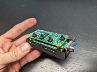
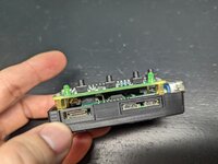
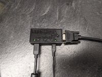
After finding external video adapters in both my Classic and SE, I've been wanting to build an RGBtoHDMI. Well, I finally got my hands on a Pi Zero and all the other parts, printed a case, and assembled one. @Mu0n 's stickied thread was a big help.
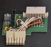
My 030 Classic came to me with this unmarked thing installed:
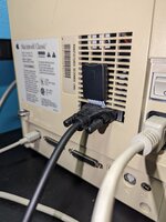
and a cable going from that 8-pin header to a DB9 that had been "installed" on the rear of the machine (I didn't cut the case, but it was a convenient channel to run an SD card extender):
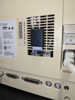
Only 4 of the 9 pins are used...ground on pin 1, video on pin 4, h-sync on pin 8, and v-sync on pin 9. This is the same pinout as the DB9 on the RGBtoHDMI's TTL buffer board, so I was able to simply use a straight-through serial cable to connect the Mac to the RGBtoHDMI:
My 030 SE had this Power R model 2703 video adapter in it, but no externally-accessible connector installed:
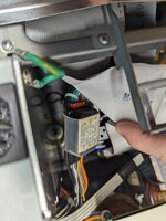
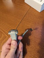
I was getting ready to build a cable when I happened to find what can only be the original cable in a random box while looking for something else. Comparing its pinout to the schematic in @Stephen 's github confirmed it:
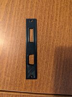
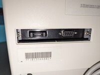
So, I printed up a bracket that would let me mount both the DB9 and an SD card extender in the SE's expansion slot while still allowing the slot cover to fit:
Even more conveniently, both of these systems use the same RGBtoHDMI profile:
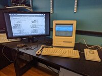
Of course, the first thing I had to do after buttoning all of this up was plug a compact Mac into the biggest screen I had for grins...and so my wife could play Oregon Trail from the couch

My 030 Classic came to me with this unmarked thing installed:

and a cable going from that 8-pin header to a DB9 that had been "installed" on the rear of the machine (I didn't cut the case, but it was a convenient channel to run an SD card extender):

Only 4 of the 9 pins are used...ground on pin 1, video on pin 4, h-sync on pin 8, and v-sync on pin 9. This is the same pinout as the DB9 on the RGBtoHDMI's TTL buffer board, so I was able to simply use a straight-through serial cable to connect the Mac to the RGBtoHDMI:


My 030 SE had this Power R model 2703 video adapter in it, but no externally-accessible connector installed:

I was getting ready to build a cable when I happened to find what can only be the original cable in a random box while looking for something else. Comparing its pinout to the schematic in @Stephen 's github confirmed it:

So, I printed up a bracket that would let me mount both the DB9 and an SD card extender in the SE's expansion slot while still allowing the slot cover to fit:


Even more conveniently, both of these systems use the same RGBtoHDMI profile:
Code:
sampling=0,0,0,0,0,0,0,0,0,0,8,0,0,0,1,0,0,0,0,1,255,100,255,100,255,255,255,256
geometry=176,23,512,342,512,342,2,2,0,1,15667200,704,5000,370,3,0,0
palette=Mono_(2_level)
scanline_level=0
Of course, the first thing I had to do after buttoning all of this up was plug a compact Mac into the biggest screen I had for grins...and so my wife could play Oregon Trail from the couch

