Testers Needed: Modified ROM for LC475/Q605

Fizzbinn

Tinkerer
Nov 29, 2021
232
232
43
Charlottesville, VA
So this might be what you were looking for
I see the post on the 68K forum, I was asking (likely poorly worded) the same thing as @zigzagjoe. Just change one variable at a time for a comparison.

Using the v092 ROM, with everything else the same, and the CPU at the default 25MHz, changing the RAM timings from 80ns to 60ns shows this improvement.

Using the v092 ROM, with everything else the same, and the CPU overclocked to 40MHz, changing the RAM timings from 80ns to 60ns shows this improvement.
 

JDW

Administrator
Staff member
Founder
Sep 2, 2021
2,194
1,806
113
54
Japan
youtube.com
Had no time to try and flash the v091 or v092 ROMs until this evening, but sadly, my ROMmate v2 programmer simply is refusing to do the job! Is the SIMM Programmer app incompatible with macOS Sequoia? I tried using my standard cable multiple times to no avail. I tried multiple USB-A to USB-C adapters to no avail. I tried other cables too, all in vain.

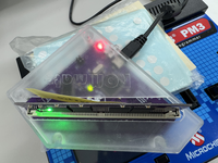
The SIMM Programmer app recognizes the ROMmate v2 programmer just fine. Meaning, I launch the app, then with the Universal ROM SIMM properly installed in the programmer, I flip the programmer's PWR SW to ON. The GRN LED on the programmer lights, as does the LED on the Universal ROM SIMM. And when programming, I get a RED LED lighting on the programmer. All is well until it finishes Verify, showing this every single time...

1759149088369.png


Identify Chips works fine...

1759149110011.png


As does Electrical Tests...

1759149122127.png


And after a Verify failure, if I try to flash again, it starts but then stops like this...

1759149154173.png


And sometimes it says that but no RED LED light on the programmer. I am forced to Restart to get it to flash again, but at the end of Verify, I get the same errors.

🤷‍♂️


JDW

Administrator
Staff member
Founder
Sep 2, 2021
2,194
1,806
113
54
Japan
youtube.com
@dougg3 I'm going nuts!

Just fired up my old Intel mid-2015 15" MacBook Pro running MacOS High Sierra and downloaded your v2.0.1 SIMM Programmer app. Sadly, when I launch the app and then switch on the ROMmate Programmer v2, the app won't recognize the programmer. 🤦‍♂️

Used Boot Camp to boot into Windows 10. Tried the Windows version. Thankfully, it can recognize the Programmer (giving further evidence that macOS High Sierra must not be supported), but sadly, it fails to flash my ROM SIMM too.

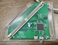
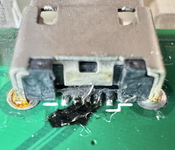
I decided to open the case and check the ROMmate Programmer v2. The back of the USB connector looks odd. Not burnt, but rather than some work had been done. My guess is that it must be that. Odd though, because it's worked fine to date.

tempImageIx0J8M.png tempImage4VlOyh.png

Well, at least I have a v1 Programmer at the office, so I'll give that a try tomorrow.
 
Last edited:

dougg3

Tinkerer
Jan 10, 2022
23
33
13
www.downtowndougbrown.com
Just fired up my old Intel mid-2015 15" MacBook Pro running MacOS High Sierra and downloaded your v2.0.1 SIMM Programmer app. Sadly, when I launch the app and then switch on the ROMmate Programmer v2, the app won't recognize the programmer. 🤦‍♂️

Uh oh! Unfortunately I don't have an actual machine running High Sierra to test against, but I can confirm that in my High Sierra VM it also isn't detected properly.

It works correctly on my Mojave VM, as well as my M2 Mac mini running Sequoia. I just flashed and verified a programmable CayMac 8 MB universal SIMM with no trouble at all in Sequoia. I'm not sure why High Sierra doesn't work, because I know I used to build this program for versions like Snow Leopard and even older. I might be able to look deeper into why it doesn't work with High Sierra in the future.

I seem to recall there was a mistake on the first revision of the boards where USB D+ and D- were swapped, so that probably explains the hack you're seeing. @Jockelill would know more about that. Mine has a bodge near the microcontroller instead of the USB port, but I'm guessing it's the same hack.

Something is definitely screwed up because it's saying "It is likely composed of mask ROMs and not programmable. If this is a programmable SIMM, there might be a problem with it." That means it's failing to detect the SIMM as actually being comprised of flash chips. What type of programmable SIMM is it? Can you try a different SIMM? I agree that testing with an old programmer would be good for narrowing down the problem.

I don't want to derail this thread into programmer troubleshooting if we have to go back and forth too much; maybe we can move to another thread or email or something. Bottom line though is that the SIMM programmer definitely works properly with Sequoia and Windows 10.
 

JDW

Administrator
Staff member
Founder
Sep 2, 2021
2,194
1,806
113
54
Japan
youtube.com
Thanks for the feedback, @dougg3 !

I don't want to derail this thread into programmer troubleshooting...
I wouldn't worry about that. I was actually rather disappointed this thread hadn't gotten more traction and largely was falling by the wayside. So this recent dialog about the programmer is a adding a nice "bump" to the thread.

I suspect that one reason people aren't adding their opinions is that many folks out there still don't have a programmer, and without that, the new firmware cannot be flashed or tested. Another issue could be that people need to acquire and solder in a ROM socket (like I did on my LC575 board) in order to even use the Universal ROM SIMM. But in my opinion, it's worth buying a Programmer and getting the socket to solder in. The pads are right there on the motherboard. It's not hard to suck out the existing solder and add a socket to the pads. So for anyone out there reading this, I'd encourage you to start having some fun with these old machines by acquiring a programmer, ROM SIMM, and ROM Socket (for your compatible motherboards).

Sadly, folks in the USA don't have any options available now, most likely due to tariffs. But for everyone else, here are the product links:
Full Disclosure, my ROM SIMM and Programmers were acquired way back in the early days, and there have been board updates since then, so my issues aren't necessarily indicative of what other owners of those devices may be seeing. Besides, I tend to be cursed anyway, having troubles no one else on earth has, so there's that. 😅


I'm at the office now with Universal ROM SIMM installed into my CayMac v1 ROMmate Programmer, and I am using the same USB cable I used last night at home without success. When I click Identify chips (again, with my v1 Programmer), it shows me this (which is expected):

1759190254135.png


Electrical tests pass:

1759190274097.png


Doing a Write to SIMM shows me Erasing first, which is expected (I mostly wasn't seeing that last night):

1759190387643.png

After that it wrote normally (at the slower 1x speed, of course):

tempImage3UFHoi.png

Verify completed successfully too...

1759190554570.png


After that, I switched off the V1 programmer and disconnected it, leaving the USB cable attached to my 2015 5K iMac running macOS Monterey, and I attached my troublesome v2 ROMmate Programmer, then switched on Power, then clicked Identify Chips, which gave me this...

1759190672110.png


So clearly, this v2 Programmer, which worked fine originally, now is bad.

I confirmed that by disconnected the v2 and reconnecting the v1, and doing Identify chips again, which passed:

1759190751689.png


So basically, I will need either a schematic or a photo that shows which traces connect to which pins on the USB connector in order to attempt a fix, but that's assuming it's only a USB connector problem and not a fried chip (which very well could happen if the USB connection was bad).

I'm not a fan of these little USB connectors because we all end up putting too much force on them during cable insertion and removal, and they aren't designed well to begin with, not having adequate size to mount permanently on the PCB. USB-A is huge in comparison, but the larger connector makes it more robust.

Also, the power switch on my v1 and v2 are both extremely close to the USB connector, such that it's always a pain to switch it ON and OFF. I can only do it by wedging my thumb at one particular awkward angle between the switch and the USB cable, and it requires a lot of force. Even when I disassemble the case and try to slide the switch with the 3D printed extender on, the switch doesn't want to slide. It's therefore probably better to just have a power switch that has a long enough plastic switch so that the plastic part extends outside the 3D printed case, and no 3D printed switch extender would be necessary.

Another issue, on my first-edition programmers anyway, is that the cut-out for the USB cable is too small. 90% of the cables I have don't fit. I only have two cables with teensy tiny black rubber around the connector that fit into the tiny case hole, and even then it requires force. I clearly need to Dremel out a larger hole to make my connectors fit into the case more easily.

I sent Will an email just now, so I'm sure we can get the v2 programmer connector issue addressed; and for now, my v1 is working fine.

Well, anyway, my battle with programmers is done, and I will test the v092 firmware by @frontein1 on my LC575 board later tonight after work.

Again, thank you for the input, Doug!

—James
 
Last edited:
  • Like
Reactions: dougg3

dougg3

Tinkerer
Jan 10, 2022
23
33
13
www.downtowndougbrown.com
So basically, I will need either a schematic or a photo that shows which traces connect to which pins on the USB connector in order to attempt a fix, but that's assuming it's only a USB connector problem and not a fried chip (which very well could happen if the USB connection was bad).

I'm glad you got something working, @JDW! I know I said I wouldn't derail the thread, but just wanted to add one more thing after your latest discoveries: to be clear, I don't think this is a USB problem at all. The fact that you are seeing good communication with the programmer software means the USB is working perfectly fine. The output of Identify Chips shows that only 3 of the 4 chips on the SIMM are responding correctly. I'd suspect at least one of the eight data bits going to IC1 has a bad connection between the main microcontroller and the SIMM socket, or it's damaged internally in the microcontroller. I can't remember off the top of my head if IC1 is D0-D7 or D24-D31, but those are the pins on the SIMM socket I'd be looking at. Maybe one of them has a cold solder joint or something. Either way, it definitely sounds like a fault on the programmer board.
 
  • Like
Reactions: JDW

Fizzbinn

Tinkerer
Nov 29, 2021
232
232
43
Charlottesville, VA
Another issue could be that people need to acquire and solder in a ROM socket (like I did on my LC575 board) in order to even use the Universal ROM SIMM.

I'm failing in my searches to find a link or other pointer (part number?) to obtain one of these ROM sockets to solder in. I feel like I've seen this somewhere but would appreciate a pointer If you have one!
 
  • Like
Reactions: JDW

JDW

Administrator
Staff member
Founder
Sep 2, 2021
2,194
1,806
113
54
Japan
youtube.com
I'm failing in my searches to find a link or other pointer (part number?) to obtain one of these ROM sockets...
I'd like to thank @Willj for his kindness in providing me with the following link, which I can now provide to all of you:


That price of $4.85 isn't too terribly bad, but that company is extremely frustrating when it comes to buying other things like RAM sockets. And for people outside the USA, they basically make it impossible to buy from them. I think they have a minimum order too.

People who buy one of the Universal ROM SIMMs from CayMac have the option to add a socket to their order, but CayMac doesn't sell the sockets separately because that would drain their inventory fast.

At some point, I think @MacEffects will need to step in and do their recreation magic by creating both RAM and ROM sockets for the community. Right now, we seem to have only New-Old-Stock sockets being sold by one major vendor in the US that isn't price-friendly toward buyers.
 
  • Like
Reactions: Fizzbinn

Fizzbinn

Tinkerer
Nov 29, 2021
232
232
43
Charlottesville, VA
Thanks @JDW! Annoying minimum order but seems like not a bad idea to have some of these.

I purchased a programer and ROM SIMM from CayMac last year to use with my Quadra 700 but didn't think about a socket to be able to use it with my Q605 (or other future Macs I might want to try a custom ROM with).
 
  • Like
Reactions: JDW

JDW

Administrator
Staff member
Founder
Sep 2, 2021
2,194
1,806
113
54
Japan
youtube.com
I've got the v092 firmware flashed to my Universal ROM SIMM in my LC575 motherboard (Color Classic Mystic). Booting into System 7.1, I see I only have 32MB RAM now instead of 36MB, which is expected. I am using the Soft 475 Overclock by @phipli to overclock my 040 CPU, but I am not seeing any changes to my benchmarks when running at various clock speeds that I ran benchmarks at in the past.

@frontein1 previously said: "LC475SetCPUClock program. But I made one change to the Config register bits for 40MHz. I changed bit 3 from 1 to 0 to allow 60ns RAM access." That's something for the 475, and not the 575. Not sure of there are specific tweaks to Phipl's software that can simulate that.

What I can say though is that previous when using Phipli's Control Strip set to 50MHz, I would most often get some level of instability. I still need to do a lot more testing, but so far, the Control Strip 50MHz setting seems to be working well.

If I used Philpli's Control Panel and Advanced Settings to set the Clock Speed to 50MHz, with Min. = Max. = 1, shortly thereafter, I get stray pixel garbage on the screen, but it still let's me run benchmarks, AND it let's me Restart without the display going black and staying black.

Overall, I can see somewhat of a positive improvement.

I am not, however, able to overlock to speeds higher than 50MHz. For example, I tried 51.7MHz via Phipli's Control Panel, and upon Restarting and loading the CP, the screen turned off (on a hardware level, and I could hear the static sound too). It still tries to boot, but there's no video. That's something I've seen in the past.

So I'm not sure if there's a good way to quantify the benefit to killing motherboard RAM (70ns) on the LC575, but if any of you have ideas, please let me know.
 

frontein1

New Tinkerer
Aug 27, 2025
14
19
3
I see I only have 32MB RAM now instead of 36MB
Do you know the speed of your RAM SIMM? If the onboard RAM is disabled during sizing, I think the MEMC still defaults to 80ns if I remember correctly. So you'd need to poke the right register to step down to 60ns. I know this works OK on the LC475, not quite sure on the LC575. But that machine also has the MEMCjr right?

I am working on a couple more changes, just taking some more time in between other stuff-
  1. For djMEMC (Wombats), I have a change ready to go to automatically support both small and large SIMMs. I think this might be net new? At least I haven't seen a copy of a ROM that has the double-pass feature during sizing.
  2. For both MEMCjr and djMEMC, I am changing how the onboard RAM is bypassed. Instead of arbitrarily setting banks to 0 if 4MB, I am purposely skipping the sizing of the onboard chips.
  3. Also I want to move the overclocking from the CDEV and INIT right into the ROM, but I think this is a bit of a more obtrusive change and I don't want people to have issues. So I may make some ROM bits configurable to control the skipping of onboard RAM and the overclock settings.
So what happens now is I have like three "v093" ROMs I am working on all for different machines :) The fun never ends.
 
  • Like
  • Love
Reactions: Jockelill and JDW

JDW

Administrator
Staff member
Founder
Sep 2, 2021
2,194
1,806
113
54
Japan
youtube.com
Do you know the speed of your RAM SIMM?

60ns

1759284472563.png


...not quite sure on the LC575. But that machine also has the MEMCjr right?
Yes. See the 4th page of the attached PDF schematic of the LC575 motherboard.

475 Overclock Software by @phipli requires MEMCjr to do its magic.

You can download the MEMCjr datasheets here:

The MEMCjr's physical location on the LC575 motherboard is found at U17 in the marked up photo below (photo by @Branchus ):

1759287252668.png


Separately from that...

Take note of this chip, which is on the LC575 board by default.

1759285623568.png


Thanks to the kindness of @trag , I was able to replace my stock MC88916DW55 chip shown above (LC575 board) with the superior MC88916DW80:

1759285596142.png


You can see below that I had the stock MC88916DW55 chip removed at U20...

1759285719062.png


Also in regards to the LC575 board, I had a detailed discussion about MOTHERBOARD RESISTORS starting with the post below and continuing on from there:


Reading through the thread is informative. But in the end, I never changed any of the resistors being discussed there on my 575 board because I don't know which to change and to what value, assuming any resistor changes are even needed.
 

Attachments

  • LC575 schematic.pdf
    6.6 MB · Views: 8
Last edited:

JDW

Administrator
Staff member
Founder
Sep 2, 2021
2,194
1,806
113
54
Japan
youtube.com
@frontein1
To supplement my previous post (you may wish to re-read that because I added edits to it throughout the day yesterday), I have even more info for you.

@phipli offers his C SOURCE CODE here:

It contains his MEMCjr configuration routines.

When using his 475 Overclock Control Panel, the "Advanced" settings look like this...

1759368002189.png


Phipli told me in the past to read the following datasheet to make sense of Ni, Mi and P settings:
https://bitsavers.computerhistory.org/components/sierra/SC11412.pdf

I still was unclear on what numbers to type into the fields (see "Advanced" dialog box above), so I spoke to Mustermann, who laid the coding groundwork for Phipli's later coding work. He told me the following in regards to the SC11412.pdf I linked above, noting that his mention of "Phipli's Tool" is referring to the 475 Overclock Control Panel and Extension combo. (Also note what Mustermann says here about Gazelle, on the LC475, being a SC11412.)

There are 2 clock generators in the [SC11412] chip. One is managing PCLK the other one is managing MCLK.
Both are programmed using a common 20-bit shift register.
DS0 (first bit) of the register decide if you are programming clock generator 1 or clock generator 2.
Within my code and Phipli's tool, DS0 is always 1 so programming clock generator 1, controlling PCLK that is connected to MC88920/16. If you switch that to 0, you can change pixelclock (but I never tried that).
Don't worry about MCLK is controlling pixelclock. Apple just used them the other way round.

Next is about "P" [field]:
There are two bits DS4 and DS5 in the shift register selecting P divider.
So this part of the register can be 00=0,01=1,10=2,11=3.
As you can see from the datasheet, 11 set divider to 1/8, 10 to 1/4, 01 to 1/2 and 00 to 1/1
My code and Phipli's tool both use the binary value of DS4 and DS5.
So at the end clock is divided by Pi(in the calculation in the datasheet) = 2^P (from the tool).
1759368848622.png
I am not sure about the greyed-out Mi/Ni ["Ni value" field].
This is how calculation works:
CPUfreq = 2 (that is what MC88920 is doing) * N/(M*2^P)* 31.3344MHz(Frequency of Crystal oscilator)
48,01238 = 2 * 95 / ( 31 * 4) * 31.3344
"Min" and "Max" [fields] are more tricky.
Both choose a set of values for different registers. This has some influence to wait states of RAM, VRAM and ROM.
As the software is not able to read the data from the shift register and so does not know the current frequency some of these registers need to be set to a minimum value and some of the need to be set to a maximum value prior switch frequency. That is where these names came from.
After switching the values are set to an appropriate other value of the the table using the same subroutines.
That is why fields are named min and max.
Phipli's tool is able to chose one of 4 datasets for min group and another one of 4 for max group.
These datasets are populated with the values proposed by the MEMCjr (memory controller) datasheet for 20Mhz, 25Mhz, 33Mhz and 40Mhz.
If you choose a lower (if i remember right it was this order) one that appropriate you may reduce wait states,
operate RAM or ROM or VRAM out of specifications but may reach higher performance.
"Min" and "Max" are setting these registers:
MEMCjr "Configuration" is setting RAM and ROM wait states
MEMCjr "RefreshInterval" is changing RAM refresh timing
MEMCjr "FrameBufferConfiguration" is setting VRAM wait states
"BIOSTimeout" is set by the ROM as well but I was not able to determine in detail what it is doing
"BIOSConfig" is set by the ROM as well but I was not able to determine in detail what it is doing
Recommended values for Configuration, Refresh and FrameBufferConfiguration can be read from MEMCjr datasheet.


I then asked Mustermann about the setregistermax & setregistermin functions in the provided C code (see "INIT.c.bin" linked above), and he provided this info:

Lets start with the setregistermax function:​
Depending on the parameter (0-3) the function set one parameter Set.​
In case level = 0 it is just doing the case 0 part.​
case 0:​
*((unsigned long*)(MEMCjrHoldingRegister)) = 0x0101>>6;​
*((unsigned long*)(MEMCjrConfiguration)) = 0x0101;​
config = 0x0000003f & *((unsigned long*)(FrameBufferConfiguration));​
config = config + ((0x0000003f & *((unsigned long*)(MEMCjrHoldingRegister)))<<6);​
config = config & 0x000000ff;​
*((unsigned long*)(MEMCjrHoldingRegister)) = config>>6;​
*((unsigned long*)(FrameBufferConfiguration)) = config;​
break;​
MEMCjr has only 6bit databus, but registers are usualy 12bit.​
So to write 12bit you need first write the upper 6bit into MEMCjrHoldingRegister and then write the lower 6bit into the target register.​
So the lines...​
*((unsigned long*)(MEMCjrHoldingRegister)) = 0x0101>>6;​
*((unsigned long*)(MEMCjrConfiguration)) = 0x0101;​
...just write 0x0101 into Configuration Register of MEMCjr.​
For the FrameBufferConfiguration register, the bits 0-7 shall not be changed by the function.​
So it first reads the register (again with support of HoldingRegister)...​
config = 0x0000003f & *((unsigned long*)(FrameBufferConfiguration));​
config = config + ((0x0000003f & *((unsigned long*)(MEMCjrHoldingRegister)))<<6);​
...then sets the bits 8-11 to 0 (that is the parameter for level 0)​
config = config & 0x000000ff;​
and write back the result​
*((unsigned long*)(MEMCjrHoldingRegister)) = config>>6;​
*((unsigned long*)(FrameBufferConfiguration)) = config;​
For Level=0​
Configuration is set to 0x0101​
FrameBufferConfiguration is set to 0x00?? (?? because these bits were not changed)​
For Level=1​
Configuration is set to 0x001A​
FrameBufferConfiguration is set to 0x00?? (?? because these bits were not changed)​
For Level=2​
Configuration is set to 0x00DC​
FrameBufferConfiguration is set to 0x02?? (?? because these bits were not changed)​
For Level=3​
Configuration is set to 0x02DC​
FrameBufferConfiguration is set to 0x0A?? (?? because these bits were not changed)​
Configuration register is setting wait states for RAM and ROM​
FrameBufferConfiguration is setting wait states for RAM and ROM​
E.g., Level 0 is 1 ROM waitstate, Level 1 is 2 ROM waitstate, Level 2 is 4 ROM waitstate and level 3 is 4 ROM waitstates.​
As all these registers are about waitstates, for security reasons.​
it is better to have more waitstates. So if frequency is between 2 datasets read from datasheet (e.g. between 25Mhz and 33Mhz the values should set to maximum of the values of the edges.​
That is why the function is named setregistermax.​
As I have a programmable ROM added to my LC475 that is quite fast (55ns, instead of 100ns or 120ns as the onboard ROM is) it makes sense for me to reduce ROMwaitstates at higher frequencies as well.​
Current version of the Extension is not able to do this.​
From my experience, ROM speed and waitstates have a significant impact to overall speed.​


Lastly, Phipli's 475 Overclock Software is COMPATIBLE with the following Macs:

• LC475, P475, P476, Q605​
• LC575, P577​
NOTE: Some Macs (not 575) need resistor changes (not LC575), as mentioned on Phipli's Web Page here.​

EDIT: For those of you who want to learn more about the 475 Overclock software, I have a comprehensive video about it.
 
Last edited: