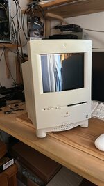
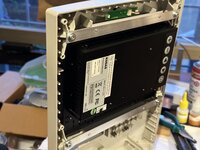
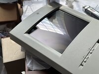
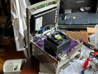
The great LCD in a Color Classic thread. Well, I wish...

Piszigri

New Tinkerer
Mar 24, 2023
12
14
3
So first things first - hello to everyone.

The reason for this post is that I am building a sort of "reverse-Mystic" or Reverse Takky, in the sense that the core idea of Takky -and of Mystic as well- is to replace the logic board with a more powerful one, leaving the original (albeit modded) Trinitron screen and analog board in the machine.

While this may have been a great idea twenty years ago, many things have happened since then. Color Classics have become scarce, for one. Second, the admittedly magnificent CRT of the CC is showing all its age, but most of all, the horribly built Analog Boards with their bean counter minded construction are slowly but surely all failing- and are unrepairable, due to many parts being custom and unobtanium (i-e- the FBT, the big CRT IC driver, all the switching PS transformers...).

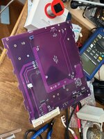
I want to replace the original Analog board with a rebuilt one that includes a PSU, supporting circuitry and a 8.4" SVGA LCD from a POS terminal, original built-in microphone support, even stereo audio amplification, and this could be a solution for many owners of such Takky/Mystics that have overburnt AB and 640x480 driven CRTs to replace them completely. In my design everything is reversible, and no permanent modification is done. At this time, only Takky/Mystics are supported due to the fact that the original 512x384 resolution is unavailable in most LCD displays.

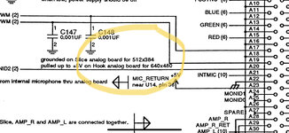
If this sounds familiar, it's because I started this thread back at 68KMLA, however i had contacted JDW because I had hit a wall in information - and I need help to complete this project. Specifically, there is missing information in regards to the pinout of the original analog board. Without this information, it seems that the logic boards installed into a CC with my SFX PSU adapter PCB fail to boot and instead give out a lot of grief. Some pins like pin 39 and pin 3 from the original AB edge connector, carry -5V unregulated, for example. I cannot find any info and cannot trace back everything on the original AB as i am not an EE.....
but, the main problem is that the analog board I am doing testing on is a failed board, without all the EHT portion and FBT.

So, I need some help from an experienced CC owner, that can trace the undocumented pins on the original and fully working AB connector, and also figure what communication is going between LB and AB of a fully booting Color Classic on so that I can replicate it and make my PCB transparent to the LB.

if and when I will be successful, I will release all Gerbers and details on how to perform the Reverse Takky and LCD mod, totally free, for anyone that wants to recover their Mystic - Takky CC to life again - and improve it with a 800x600 LCD screen too!

Original MLA thread:
https://68kmla.org/bb/index.php?threads/the-color-classic-lcd-project.44829/

Thank you JDW for your help and support!
 

Attachments

  • 1.jpeg
    1.jpeg
    618.8 KB · Views: 452
  • 2.jpeg
    2.jpeg
    866.1 KB · Views: 158
  • 3.jpeg
    3.jpeg
    1.1 MB · Views: 167
  • 4.jpeg
    4.jpeg
    62.3 KB · Views: 177
  • 5.jpeg
    5.jpeg
    179.5 KB · Views: 169

Kai Robinson

TinkerDifferent Board President 2023
Staff member
Founder
Sep 2, 2021
1,292
1
1,281
113
43
Worthing, UK
For 512x384 - you could get a 1024x768 (exactly double) LCD panel and use a 2x scaler?
 

Piszigri

New Tinkerer
Mar 24, 2023
12
14
3
Hey Kai - yes, that is a very viable possibility, as the graphics stream of the lb is routed directly to a connector outputting rgb plus composite sync so a prescaler or other analog video device can easily be placed between the lcd monitor and lb. However, that is an easy detail once I figure out the problem preventing booting in the project… i feel Im so close. I really need some help in tracing back the pins and whatever protocol the cc follows!

eta:
one thing that could be checked, provided a fully working CC is available, is whether there’s a simple communication protocol like I2C going on with the big ASIC in the shielding that drives the CRT.
Or it could be simple as the brightness controls need to be “loaded” in some way - theyre disconnected at this time…..
 
Last edited:

alxlab

Active Tinkerer
Sep 23, 2021
293
323
63
www.alxlab.com
This sounds like an interesting project. You wouldn't happen to have the pinouts you've worked out so far posted anywhere would you? I didn't notice them on the original 68kmla post.

Regarding the edge connector of the logic board and analog board, we could probably make one out of a separate PCBs and pin headers.

The logic board would need a 2mm PCB. The analog board would need a 1.6mm PCB. The pin spacing is 2.54mm for the non power part.
 

Piszigri

New Tinkerer
Mar 24, 2023
12
14
3
Hi, that is an interesting concept, I have to try and design something in DipTrace, maybe you got something there! Sure, once I vet. Ack from a week of well deserved holiday at the seaside i’ll post what I found out and maybe we can figure whats going on with the rest of the pins.
franco
 

eric

Administrator
Staff member
Sep 2, 2021
1,111
1,834
113
MN
bluescsi.com
This looks like a great project! I've been trying to source a new CRT for my CC but have had no luck and broken tubes in shipping (even though very well packed)

Keep us updated on the status and if you need help - I'd be willing to dig out my broken CC parts to help make it whole again. (busy getting ready for vcf-mw the past few weeks!)
 
  • Like
Reactions: Piszigri

Piszigri

New Tinkerer
Mar 24, 2023
12
14
3
Hey Eric, I’m waiting for an intact harness and cage from a CC that a kind MLAer gifted me to build a functional but “open” cc that I can probe during operation to document each pin, so to duplicate it. I may need a healthy analog board for non-destructive testing at one point, but that is the next step…
up to now I have been working with the info published in all of the takky and mystic mod websites but it’s not enough! And already have found inconsistencies.
 

Piszigri

New Tinkerer
Mar 24, 2023
12
14
3
Update: a cage and harness is on ghe way to me, courtesy of “cheesestraws”! And, I laid my hands on two Apple Original (tm) schematics, one of the LC-575 Logic board and the second of the Color Classic. Both detail the Foxconn connector with all signals therefore the goal is nearer than ever! A surprise is that according to the CC schematic notes there is a 640 resolution setting the Splice LB may be capable of, but it is only mentioned.
 

Attachments

  • IMG_2641.jpeg
    IMG_2641.jpeg
    293.5 KB · Views: 116

Piszigri

New Tinkerer
Mar 24, 2023
12
14
3
So, the surprise is not that “Hook” - or 5xx series - has a 640x480, rather that the Splice (or CC) may possibly drive a 5xx analog board for the higher res. Can anybody confirm that placing a CC LB in a 520-575 results in a functioning system? Sense lines are set on the AB after all, not the LB.
 

David Cook

Tinkerer
Jul 20, 2023
75
93
18
So, the surprise is not that “Hook” - or 5xx series - has a 640x480, rather that the Splice (or CC) may possibly drive a 5xx analog board for the higher res. Can anybody confirm that placing a CC LB in a 520-575 results in a functioning system? Sense lines are set on the AB after all, not the LB.
Color-Classic-Motherboard-in-Performa-550.jpg


Yes. It works fine and defaults to 640x480. This is an unmodified Color Classic motherboard (LB) in an unmodified 550 (analog board + display). Extra VRAM is not installed, hence 16 colors.
 

David Cook

Tinkerer
Jul 20, 2023
75
93
18
Upgrading the Color Classic board with +256KB of VRAM allows it to display 256 colors @ 640x480 when installed in the Performa 550.
 

Piszigri

New Tinkerer
Mar 24, 2023
12
14
3
This makes the whole project even more interesting! The LCD in a CC will be compatible with LBs from the CC, CCII, 520, 550 and 575 - all with display resolution of 640x480! The 575 may also get 800x600 with this design. need to place a couple jumpers to set resolutions and it’s going to be great.
 
  • Like
Reactions: wottle

JDW

Administrator
Staff member
Founder
Sep 2, 2021
2,238
1,835
113
54
Japan
youtube.com
@Piszigri

I spotted your post in that other forum today...

1759796439852.png


It will be interesting to see how your excellent kit develops once it becomes impossible for anyone to source that particular LCD anymore.

For now, I've been looking for more photos of how the GVision display looks in its native resolution while installed into a CC. I found a couple photos on the MLA, but nothing that really lets you pixel peep.

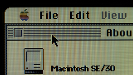
Having installed the LCD Color Kit for the SE/30 by ZZJ, I can attest to how bright and sharp and beautiful that display is — it's quite shocking. Despite NOT being an IPS display, viewing angles are incredible. For example, here is a photo that I took of that display (click on it and zoom in to revel in the sharpness!)...

1759796825630.png

And so, I am just wondering if there are similar photos out there for your chosen LCD for the Color Classic. If not, and if you have no means to take them, perhaps you could simply describe the difference in words?

Thank you!
 

ESM-NL

New Tinkerer
Jun 4, 2025
29
23
3
The Netherlands
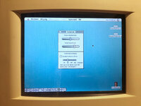
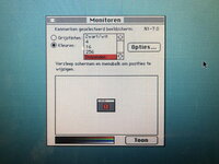
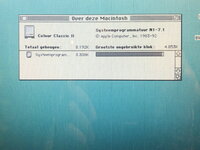
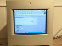
I bought this Color Classic LCD set last june. Here some of the photos I posted over there after installing. Take in considderation that they are taken with an iPhone 8.
 

Attachments

  • 15_CC_2.jpg
    15_CC_2.jpg
    340.6 KB · Views: 21
  • 19_screen_monitor.jpg
    19_screen_monitor.jpg
    382.7 KB · Views: 20
  • 20_screen_about.jpg
    20_screen_about.jpg
    495.8 KB · Views: 21
  • 22_screen_mac_garden.jpg
    22_screen_mac_garden.jpg
    217.1 KB · Views: 20
  • Like
Reactions: JDW and jibsaramnim

daanvdl

New Tinkerer
Feb 8, 2023
4
4
3
Netherlands
Just diving in — I actually designed the analog video section and board for this particular LCD-CC kit with the curved glass frame.

Yes, it’s running 640×480 on an 800×600 panel. It works surprisingly well, though there’s a bit of visible upscaling here and there.
I’m still quite happy that I managed to get a stock Macintosh Classic running at 640×480 (16 colors, of course, if you’re using the standard 256 KB VRAM) — but it looks great nonetheless.

Right now I’m experimenting with some LVDS 800×600 LED panels and custom driver boards for this kit. I really want to add support for 512×384 at that odd refresh rate — and my first tests are looking promising! To be continued! 😉
 
  • Like
Reactions: JDW and ESM-NL

jibsaramnim

New Tinkerer
Mar 16, 2024
35
24
8
South Korea
davejansen.com
Right now I’m experimenting with some LVDS 800×600 LED panels and custom driver boards for this kit. I really want to add support for 512×384 at that odd refresh rate — and my first tests are looking promising! To be continued! 😉

Out of curiosity as a fellow CC fan quite curious about your LCD replacement project; would a 1024x768 panel like the Eyoyo one @JDW has mentioned in some of his videos perhaps be a viable, pixel perfect option?
 

JDW

Administrator
Staff member
Founder
Sep 2, 2021
2,238
1,835
113
54
Japan
youtube.com
…I managed to get a stock Macintosh Classic running at 640×480 (16 colors…

Not that the LCD kit displays only 16 colors, but that your custom-built Analog Board, when driving the stock CC’s CRT (not the LCD) can only produce 16 colors due to its limited VRAM?
 

ESM-NL

New Tinkerer
Jun 4, 2025
29
23
3
The Netherlands
The 16 colors limitation is only caused by the 640x480 resolution. With the original resolution with the CRT, and a standard 256k VRAM, you have 256 colors. I have an extra 256k VRAM in my CC+LCD and have 256 colors with 640x480.

With an LC550/CCII board, 512k VRAM is standard and with an extra 256k VRAM, you have 32768 colors at 640x480.