So first things first - hello to everyone.
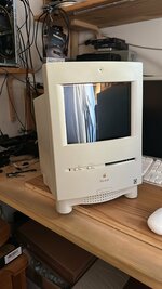
The reason for this post is that I am building a sort of "reverse-Mystic" or Reverse Takky, in the sense that the core idea of Takky -and of Mystic as well- is to replace the logic board with a more powerful one, leaving the original (albeit modded) Trinitron screen and analog board in the machine.
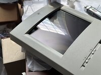
While this may have been a great idea twenty years ago, many things have happened since then. Color Classics have become scarce, for one. Second, the admittedly magnificent CRT of the CC is showing all its age, but most of all, the horribly built Analog Boards with their bean counter minded construction are slowly but surely all failing- and are unrepairable, due to many parts being custom and unobtanium (i-e- the FBT, the big CRT IC driver, all the switching PS transformers...).
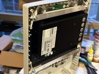
I want to replace the original Analog board with a rebuilt one that includes a PSU, supporting circuitry and a 8.4" SVGA LCD from a POS terminal, original built-in microphone support, even stereo audio amplification, and this could be a solution for many owners of such Takky/Mystics that have overburnt AB and 640x480 driven CRTs to replace them completely. In my design everything is reversible, and no permanent modification is done. At this time, only Takky/Mystics are supported due to the fact that the original 512x384 resolution is unavailable in most LCD displays.
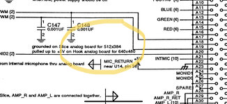
If this sounds familiar, it's because I started this thread back at 68KMLA, however i had contacted JDW because I had hit a wall in information - and I need help to complete this project. Specifically, there is missing information in regards to the pinout of the original analog board. Without this information, it seems that the logic boards installed into a CC with my SFX PSU adapter PCB fail to boot and instead give out a lot of grief. Some pins like pin 39 and pin 3 from the original AB edge connector, carry -5V unregulated, for example. I cannot find any info and cannot trace back everything on the original AB as i am not an EE.....
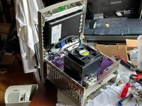
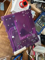
but, the main problem is that the analog board I am doing testing on is a failed board, without all the EHT portion and FBT.
So, I need some help from an experienced CC owner, that can trace the undocumented pins on the original and fully working AB connector, and also figure what communication is going between LB and AB of a fully booting Color Classic on so that I can replicate it and make my PCB transparent to the LB.
if and when I will be successful, I will release all Gerbers and details on how to perform the Reverse Takky and LCD mod, totally free, for anyone that wants to recover their Mystic - Takky CC to life again - and improve it with a 800x600 LCD screen too!
Original MLA thread:
https://68kmla.org/bb/index.php?threads/the-color-classic-lcd-project.44829/
Thank you JDW for your help and support!
The reason for this post is that I am building a sort of "reverse-Mystic" or Reverse Takky, in the sense that the core idea of Takky -and of Mystic as well- is to replace the logic board with a more powerful one, leaving the original (albeit modded) Trinitron screen and analog board in the machine.
While this may have been a great idea twenty years ago, many things have happened since then. Color Classics have become scarce, for one. Second, the admittedly magnificent CRT of the CC is showing all its age, but most of all, the horribly built Analog Boards with their bean counter minded construction are slowly but surely all failing- and are unrepairable, due to many parts being custom and unobtanium (i-e- the FBT, the big CRT IC driver, all the switching PS transformers...).
I want to replace the original Analog board with a rebuilt one that includes a PSU, supporting circuitry and a 8.4" SVGA LCD from a POS terminal, original built-in microphone support, even stereo audio amplification, and this could be a solution for many owners of such Takky/Mystics that have overburnt AB and 640x480 driven CRTs to replace them completely. In my design everything is reversible, and no permanent modification is done. At this time, only Takky/Mystics are supported due to the fact that the original 512x384 resolution is unavailable in most LCD displays.
If this sounds familiar, it's because I started this thread back at 68KMLA, however i had contacted JDW because I had hit a wall in information - and I need help to complete this project. Specifically, there is missing information in regards to the pinout of the original analog board. Without this information, it seems that the logic boards installed into a CC with my SFX PSU adapter PCB fail to boot and instead give out a lot of grief. Some pins like pin 39 and pin 3 from the original AB edge connector, carry -5V unregulated, for example. I cannot find any info and cannot trace back everything on the original AB as i am not an EE.....
but, the main problem is that the analog board I am doing testing on is a failed board, without all the EHT portion and FBT.
So, I need some help from an experienced CC owner, that can trace the undocumented pins on the original and fully working AB connector, and also figure what communication is going between LB and AB of a fully booting Color Classic on so that I can replicate it and make my PCB transparent to the LB.
if and when I will be successful, I will release all Gerbers and details on how to perform the Reverse Takky and LCD mod, totally free, for anyone that wants to recover their Mystic - Takky CC to life again - and improve it with a 800x600 LCD screen too!
Original MLA thread:
https://68kmla.org/bb/index.php?threads/the-color-classic-lcd-project.44829/
Thank you JDW for your help and support!