JDW

Administrator
Staff member
Founder
Sep 2, 2021
2,078
1,742
113
54
Japan
youtube.com
All of us who have done the 68.4V "VGA Mod" on our Mac Color Classic ANALOG BOARDS know that you must change the SENSE LINES, and that involves ISOLATING pin-25. I did that, along with @Branchus and @Kay K.M.Mods and countless other people through the years, and none of us have any problems doing it the same way. But while preparing for my forthcoming video on the 84v 13" Hi-rez mod conversion, I discovered something I hadn't thought about before. And honestly, I don't think anyone has!

Have a look at the sense line mod area on the bottom of the ANALOG BOARD in my marked-up photo below...

1755332323815.png

(The board above is Rev. C.)

When doing the VGA Mod, we remove the 0Ω resistor at J78 (on boards that have it) in order to isolate pin-20 from Ground. (For the 84V 13" High Resolution mod, we move that 0Ω resistor (jumper) from J78 to J79, which effectively ties pin-20 to +5v.) The VGA Mod also requires isolating pin-25, but closely examine the width of the trace leading to pin-25. Ponder that trace-width deeply.

Specifically, note how incredibly thick that GND trace is leading to pin-25. Sure, it narrows going up to pin 25, but it then widens at the GND rail. That GND rail branches off along the edge of the PCB to feed GND to 4 other pins.

When doing the 68.4V VGA Mod, we are told that pin-25 must be isolated, and indeed it must be, but there are implications to that. In order to isolate it, we are all told to cut above and below pin-25. And truly, there is no other way to isolate pin 25. But consider this. When you cut out pin 25, that thick GND trace no longer feeds GND to the 4 pins!

Pin-32 is probably not affected because it leads to RS6, and those pads are empty. But what of pins 18, 36 and 38?

On the component side of the ANALOG BOARD there is a metal shield hiding the components, and I didn't want to bend the twisted feet on the solder side to get it off, so I cannot check the connections on top of my CC Analog Board. I can only assume that one of those pins must be tied to ground elsewhere (at the motherboard), otherwise, if pin-25 was the only GND source, pins 18, 36 and 38 would be left floating.

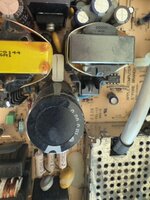
Unwilling to give up, I search for another 2 hours and then remembered Kay Koba's blog. Very useful! The photo below was found on this blog page, where Kay shows the LC575 Analog Board converted for use in his CC, and he has that metal cover removed on the component side, revealing not much other than a single yellow tantalum capacitor near the power pins, and the rest are just metal staple jumpers. The CC Analog Board is quite similar, so I have little doubt it is probably about the same as shown below. In other words, see that isn't helpful to know how pins 18, 32, 36 and 38 are affected when pin 25 is fully isolated and GND is cut-off to that GND rail.

1755338702024.png


Any thoughts?


Some of you may wonder why this even matters, and the reason is because when switching from the VGA Mod to the 84V Mod, you have to put pin-25 back the way it was before. It's easy to ground Pin-25 by soldering a short wire to the adjacent pin (pin 26) that once fed GND to it. But it also seems logical to reconnect the other side of pin-25 too, so that GND rail feeds pins 18, 32, 36 & 38 again. Rather than scraping off the green UV solder mask and soldering a wire from pin-25 to that GND rail, it would be easier to just solder a wire from pin-25 to pin-32. Soldering pin-26 to pin-32 would accomplish the same thing. Yeah, the trace leading from pin-32 to the GND rail is thin, but when you consider that isolating pin-25 cut off all GND to the GND rail, and yet everything still worked fine, soldering a GND wire to pin-32 to feed the GND rail probably will suffice.

And if you're wondering if I have consulted the partial (and very INCOMPLETE) Analog Board PCB layout found here, the answer is yes, and I even put pin numbers on it for clarity. But "incomplete" is the key word here. Note the mistake it makes below by not drawing a white line from the GND rail to pin 32. So in light of that oversight, I cannot really trust that PCB layout, and it doesn't show me anything helpful anyway.

1755335769826.png
 

Paolo B

Tinkerer
Nov 27, 2021
280
163
43
Switzerland
Below my take: I just desoldered and removed pins 20 and 25.
It did work. Until today, when after many months and a intercontinental relocation in between, I restarted my Mystic for the first time.
This time at 220V. A suspicious “pop” at the start up as the machine got energized and the display now looks messed up.
Don’t know if this has anything to do with the modification in combination with 220 V, though.
At a first glance, the neck board has what seems to me as a blown capacitor, any advice is more than appreciated.

IMG_0004.jpeg
IMG_0002.jpeg
IMG_0005.jpeg
IMG_0006.jpeg
 
  • Wow
Reactions: JDW

JDW

Administrator
Staff member
Founder
Sep 2, 2021
2,078
1,742
113
54
Japan
youtube.com
DV means diode, and I think I see the Cathode line marking on the side closest to that DV11 silkscreen.

Determining the type of diode and its part number is crucial for replacement.

I see that @Mu0n has a nice photo here:
@MuOn, would you know the value of that DV11 diode?

I see a partial description in the CC Analog Board Parts List here (keyword search for DV11 to jump to it):

I told ChatGPT it's an SMD diode with "BGF (possibly E, not F?) 1G G1" and asked it to research what it might be. It came back saying this:

1755440541688.png


@Paolo B , could you explain how you removed pins 20 & 25 entirely? If you have the metal shield removed on the component side of the board, I love to see a photo of that area.

I also see that you have an analog board which is missing J78 & J79, so how you must treat the Sense Lines depends on which VGA mod you have. Do you have the 68.4 V version or the 84V 13” Hi-Rez version?

I have to start my work day early tomorrow so I'm off to bed, but I hope the above helps a little.
 
  • Like
Reactions: Paolo B

Paolo B

Tinkerer
Nov 27, 2021
280
163
43
Switzerland
DV means diode, and I think I see the Cathode line marking on the side closest to that DV11 silkscreen.

could you explain how you removed pins 20 & 25 entirely? If you have the metal shield removed on the component side of the board, I love to see a photo of that area.

I also see that you have an analog board which is missing J78 & J79, so how you must treat the Sense Lines depends on which VGA mod you have. Do you have the 68.4 V version or the 84V 13” Hi-Rez version?

Thanks for the feedback and the support.

DV11 is a diode, sure. At a closer inspection it seems to be labelled "BGF 1G G1".

As for the pins 20 and 25, stupidly I did not document the process. However, please see in the picture how it looks from the back, underneath the metal cage. Both pins desoldered and lifted (yes, I had to desolder the entire connector, this much I do remember), plus a bridge.

Concerning the modification, I went for the basic 68.4 V one. Everything worked fine for quite some time, until today.

79CADF96-C4A0-4764-8E1C-23DAF455F60C_1_201_a.jpeg


1755449603662.jpg
 

JDW

Administrator
Staff member
Founder
Sep 2, 2021
2,078
1,742
113
54
Japan
youtube.com
Wow! The fact you desoldered that entire connector is incredible!

I really must go to work now, but I just wanted to post a little extra for you, so you have something to ponder.

The book Doping Mac, which @Kay K.M.Mods sells and recommended to me, shows that when doing the 84V 13" Hi-Rez Mod on boards like yours WITHOUT the J78/J79 jumper pair, a pull-up resistor must be used as follows:

1755468078268.png


But you are NOT using the 84V mod but instead using the 68.4V VGA mod, which means you DO NOT use that 4.7kΩ resistor at all and instead isolate pin-20 (which it seems you have done), and then connect Pin-20 to Pin-24 with a jumper wire, which seems like you have done based on your photo here...

1755468208079.png


Hmmm...


I took the photo posted on the MLA by @Mu0n and flipped the left side photo horizontally in order to identify pin numbers on that yoke connector, which you can see as follows:

1755467759356.png


So the Anode of that DV11 diode connects to pin-11 and the Cathode connects to a thick trace that leads to pin-13 and many other places.

Alas! I must go to work now and must defer thoughts to later. For now, I guess the important question is this: Is that DV11 diode burned or otherwise really bad? Or is it something else? Because your latest photo of that diode clearly shows its 3 lines of text, and it doesn't look burned in that photo...

1755468336500.png


Also, I'm pondering what you said here...

It did work. Until today... I restarted my Mystic for the first time. This time at 220V. A suspicious “pop” at the start up as the machine got energized and the display now looks messed up.

Even though the CC was designed to work on 100VAC or 120VAC or 220VAC, I suspect the higher voltage may put more strain on the CC’s aging components. So we cannot necessarily say if the VGA Mod you have installed is the root cause.

What lead you to remove and open the Yoke Board and then spot Diode DV11? Did you inspect the Analog Board fully, find nothing, then open the Yoke Board as a last resort?

Your diode looks like it might be bad in your first photo, but then in your zoomed-in photo showing the markings, it looks fine. I’m afraid the only way to know if that diode is bad would be to desolder and check it with a meter set to diode check. But you would then need to take great care to solder it back with the Cathode line going in the same direction as before.

If you did not check your Analog Board fully, note the degauss component is there to remove discolorations, and you have discolorations. There’s a screen capture from my last video…

1755478466393.png


Do you hear the normal noises when you press the Power Key on your keyboard?
When I do that on my CC, I hear a static like sound just before the CRT lights up.
 
  • Like
Reactions: Paolo B

Paolo B

Tinkerer
Nov 27, 2021
280
163
43
Switzerland
Wow! The fact you desoldered that entire connector is incredible!

Thanks for you support, I really appreciate it!

Desoldering the whole connector has not been particularly difficult, even with a basic desoldering station like the one I have.
I just wanted to avoid altering the board, so I figured out the least invasive solution possible.

As for the current issue, I immediately noticed that even before the start up chime, almost instantly as I pressed the power button on the keyboard, a suspicious "pop" came out loud. To the point I was expecting nothing to appear on the screen. Luckily - so to speak - this has not been the case, but still some damage occurred.

As I couldn't see any visibly damaged component on the analog board (beyond the almost charred board behind the overheating resistors and diodes), I checked the CRT neck board noticing this overheated (damaged?) diode.

I now checked the degaussing item you highlight, seems to be OK, at least I could not spot any visible damage.

I need unfortunately to set this project aside for a few weeks, so for the moment being I can't run any further check.
 
  • Like
Reactions: JDW

JDW

Administrator
Staff member
Founder
Sep 2, 2021
2,078
1,742
113
54
Japan
youtube.com
@Paolo B , because you said you won’t have the ability to test for a few more weeks, I’m going to write a few words below that take this thread back to the question I asked in my opening post because I’d like to get some thoughts from other CC owners.

I’m in the middle of filming a video about converting the 68.4V VGA mod to the 84V 13” High Resolution mod. The discoveries made in that process led me to create this thread. I asked a question in the opening post which has not yet been answered. It’s perhaps a difficult question, and one that nobody has asked before, so that perhaps explains the lack of attempts to answer it. Nevertheless, I’d like to direct everyone’s attention to that question again in hopes of getting some feedback. And to make my question CRYSTAL CLEAR, I will offer you the following...

Yesterday, I fully removed my Analog Board and measured between GROUND and Pins 18, 32, 36 and 38.

1755562103233.png


I found Pins 18, 32, 36 and 38 were not Grounded by the Analog Board. No surprise there because of what I said in my opening post — we CUT THEM OFF when doing the VGA Mod, when isolating Pin 25..

My Analog Board has the standard 68.4V VGA mod installed. My board also has J78 & J79 jumpers. I did the VGA mod in strict accordance with the book Doping Mac, which is how everyone does that mod. (Well, everyone except @Paolo B , who removed the entire connector in order to lift pins instead of isolating them by cutting. Also note that his board lacks J78 and J79.)

As mentioned in my opening post, the VGA mod says to isolate pin-25 by cutting the copper trace between 25 & 26, and also cut the thick trace on the opposite side of Pin-25 that attaches to the Ground Rail that feeds Pins 18, 32, 36 and 38.

So, as mentioned in my opening post, when you make those two cuts at Pin-25, two things happen:

  1. Your effectively isolate Pin 25. That is a requirement for the standard VGA mod. (In contrast, Paolo isolated his Pin 25 by LIFTING the Pin and NOT cutting, thereby maintaining Ground to Pins 18, 32, 36 and 38.)

  2. Cutting means the Analog Board no longer feeds Ground to Pins 18, 32, 36 and 38, and I confirmed that last night by testing with my meter.

Of course, I tested with the machine torn apart and the motherboard no longer connected. So I don’t know if the motherboard is supplying ground to those Pins. That's why I created this thread — to find out.

When everyone does the VGA mod, it usually just works. So no one thinks beyond what they’re told to do. But is the motherboard Grounding those pins without help from the Analog Board?

If it can be shown that the motherboard DOES ground those Pins, then my question would then be answered, and it won't matter that you’ve isolated Pin 25 by CUTTING in those two places.

But if the motherboard is NOT grounding the aforementioned Pins (and I have no idea if that’s true), it means they’re not being Grounded at all when you CUT in two places to isolate Pin-25 for the VGA Mod. And because we don’t really know what those Pins do (18, 32, 36 and 38), we don’t know the implications of cutting-off ground to them.

But let’s hypothetically say the motherboard is grounding them. Why then does the Analog board also ground them? It doesn't make a lot of sense, and that leads me to doubt if the motherboard is actually grounding them. Because if the motherboard is grounding them, the analog board wouldn’t need to, especially because I don’t believe its passing high current to those pins.

So again, I look forward to hearing from you Color Classic experts regarding this.

Thanks.

(I’m going to tag @techknight and @SuperSVGA who may not have spotted this thread.)
 
  • Like
Reactions: Paolo B

JDW

Administrator
Staff member
Founder
Sep 2, 2021
2,078
1,742
113
54
Japan
youtube.com
Sometimes posting photos helps to attract much needed attention to a thread, so here are some very high resolution photos of the top and bottom of my Analog Board, as well as zoom shots of the 68.4V VGA Mod (Sense Lines & Horizontal Deflection Voltage areas). You'll also see I have the stereo mod installed too. :)

If you look closely at the PCB bottom photo and look at the middle-left area, you'll see the solder mask over those traces has become darker than the other traces due to heat. That's the area where I swapped out resistors and diodes for higher wattage versions.

AB-TOP.jpg AB-BTM-VGAmod.jpg

AB-Sense-Lines.jpg AB-Horiz-Defl-Volt.jpg
 

Paolo B

Tinkerer
Nov 27, 2021
280
163
43
Switzerland
So, eventually, as I just didn't want to have another gut open Mac around, I reassembled it and... surprise, the issue is now gone.
I have not modified anything, but could be that some cracked solder joints got somehow re-seated in the process.
So, yeah, most likely it was the degauss thermistor.
Will check as soon as I have some time.
@JDW Thanks for your support!

FC4F0925-0FE6-44B5-8124-1B1D01D3F631_1_100_o.jpeg
 
  • Love
Reactions: JDW

JDW

Administrator
Staff member
Founder
Sep 2, 2021
2,078
1,742
113
54
Japan
youtube.com
@Paolo B
So you’re saying that when you heard the pop and saw the CRT discoloration problem, you had the rear case removed?

The reason I ask is because how the very back and bottom of the machine (the metal shield) sits on your desk is crucial because that can impact the small, curved pieces of metal that are supposed to make contact with the bottom of the motherboard for the sake of proper grounding. Even a small ADB cable that somehow slipped its way under the very back and bottom of the machine could press up against it in a way that could cause an intermittent ground, which in the could cause some unexplained problems.

That still leaves the question of what that pop sound really was though. Because if it was an exploding capacitor or Yoke Board diode that suddenly burned, I wouldn’t expect the machine to start working properly once the rear case is put back on.

Regardless, I’m really quite pleased and excited that your machine is working properly now, though!
 
  • Like
Reactions: Paolo B

Paolo B

Tinkerer
Nov 27, 2021
280
163
43
Switzerland
That still leaves the question of what that pop sound really was though.

There’s a crack in the case of one capacitor (?) tucked between two transformers (?) and a big capacitor. Could be it was that, I need to desolder it.
Now the Mac is back in the closet and there will remain for some time.
I am planning to implement the stereo mod following your tutorial, I will then go again through the analog board, too.
Thank you!
 

Attachments

  • IMG_0011.jpeg
    IMG_0011.jpeg
    60.8 KB · Views: 7
  • Like
Reactions: JDW

JDW

Administrator
Staff member
Founder
Sep 2, 2021
2,078
1,742
113
54
Japan
youtube.com
Hmmm... You have a different capacitor part number than I do. Mine is blue and shaped slightly differently (with no crack, of course)...

1755753973005.png


Because you confirmed your machine working, that indicates the plastic housing of your capacitor cracked, but nothing inside was affected. Even so, if that truly is a crack, it's worth replacing that capacitor, especially before you embark on the Stereo mod.
 
  • Like
Reactions: Paolo B