SE/30 noise in video - where do I look next?

basslinemz

New Tinkerer
Nov 16, 2025
2
0
1
I'm new to this forum, and fairly new to some aspects of vintage computer repair even though I've used 'em since they weren't vintage. I've dug through these forums and others but not seen an issue quite like the one I'm dealing with.

I've got an SE/30 that, until this past year, I didn't even know worked - I was given it along with several other partial compact Macs by a friend years ago, and they sat in a shed that wasn't terribly watertight, so when I dug them out for a project, there was plenty of surface rust, and the mainboard was a bit crusty looking, but fortunately not battery bombed. After a reasonable cleaning, and wiggling the ROM SIMM a bit, it came to life, and it's got an external video card in it, even!

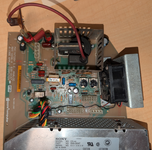
In the process of making it more presentable, I've swapped the analog board for a spare from an SE that had a good flyback transformer, recapped THAT board, the power supply and the mainboard with kits from Console5, put a new battery in and replaced the HDD (which I managed to get working enough to back up) with a BlueSCSI. It now boots (and chimes) and runs reliably, and for the most part, looks great.

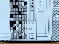
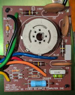
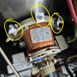
Except there's noise in the video that gets stronger as it warms up - after about ten minutes, it reaches a peak and stays there. I saw it surge with HDD activity while I was working on recovering the files that came with it, but that part isn't in the machine. I've tried replacing the HOT and reflowed the analog and CRT boards, but am unsure where to look next. The caps on the mainboard leaked at least a little, at least judging by how they looked when I removed the old ones, but I don't see much of anything that looks like corrosion beyond all the solder on the board being dull and slightly soft (fuzzy?) looking - no green crud. All of the pads came clean easily and everything looked good to my eyes otherwise. I swapped the CRT board with the one from the SE, and the noise changed a bit but didn't go away. The only consistent thing I can to to reduce the noise is to turn down the brightness - the brighter it is, the stronger the noise is. The pictures attached show this at normal brightness (the noise moves randomly like static) and one turned almost to nothing, edited to be more visible. I also haven't seen any rogue solder or bridged connections, though it's always possible that I missed one.

Would the CRT board be the next thing to investigate, or should I still be looking at the motherboard or somewhere else? I've always been good to hang parts, and now I feel more confident I can solder them, but circuit-level diagnosis is still kinda new to me.

SE30 bright 2.jpg
SE30 very dim.jpg
 

Attachments

  • SE30 bright 1.jpg
    SE30 bright 1.jpg
    1.4 MB · Views: 44

muse

New Tinkerer
Nov 3, 2025
27
17
3
This is likely a bad cap on the analog board based on your post. There is a capacitor adjacent to the flyback which has likely started to fail and is leaking.

It might not be obvious from the component side but will be clearly visible after removing it or from the solder side where the electrolyte tends to wick through.

Recap is necessary on all three boards ( logic, analog and psu ).

I used a slightly higher voltage rated electrolytic near the flyback ( 50v ) as I think the original voltage rating is underspeced and that seems to be a common failure in the analog.board.
 

JDW

Administrator
Staff member
Founder
Sep 2, 2021
2,427
1,922
113
54
Japan
youtube.com
Welcome to TinkerDifferent!

I've swapped the analog board for a spare from an SE that had a good flyback transformer, recapped THAT [analog] board, the power supply and the mainboard with kits from Console5, put a new battery in and replaced the HDD (which I managed to get working enough to back up) with a BlueSCSI. It now boots (and chimes) and runs reliably, and for the most part, looks great.
With the exception of the floppy drive (which doesn't matter in this case), you clearly have a fully recapped machine.

Not only that, but you also did this...

I've tried replacing the HOT and reflowed the analog and CRT boards, but am unsure where to look next.
By HOT you mean the BU406, correct? If so, great call. Reflowing all the connector joints was also a good call too.

1763515263631.png


Just to be clear, you are citing the problem of little wave-shaped oddities that look like this...

1763514754083.png


QUESTION: You said you swapped the analog board. That made ZERO difference? If so, what about the Yoke Board and its connector? Dirty?
 

ArjenCNX

Tinkerer
Oct 20, 2025
48
40
18
I'd second that, noise is likely from the analog board, and likely related to capacitors, im not sure if you have swapped out all electrolytics, but if you have not, i suggest you do. also make sure to re-solder the flyback transformer and coils on the board, flybacks and essentially all magnetics vibrate at the switching frequency they are exposed to, this is real high-freq mechanical vibration that will eventually weaken the solder bond so it is standard (best) practice to always re-solder any magnetics part while servicing. Also, your power supply needs the same treatment, it could also be the cause of this fault, for safety reasons you really should re-cap that as well, if that has not happened yet. it seems the high-voltage line that supplies the flyback circuit could be "dirty" (meaning there are significant AC signals on what should be a clean DC supply)
 

muse

New Tinkerer
Nov 3, 2025
27
17
3
It could also be a result of the 4 SMD capacitors around the analog video section on the logic board which havent been replaced yet..

It would be interesting to know which power supply, the ASTEC seems to have more trouble than the Sony. But this results in wavy video swinging back and forth rather than jittery/distorted lines on the screen.
 

basslinemz

New Tinkerer
Nov 16, 2025
2
0
1
Some clarifications:

-As mentioned in my original post, I HAVE recapped the analog board, power supply (Sony P/S, BTW) and mainboard, using kits from Console5. There are a few film capacitors that were not included, or even listed, for the analog board so those are original still. I cleaned as I went, so at least every place a cap got replaced is thoroughly cleaned, and I've gone over the parts more than once with IPA and a brush.

-I swapped the analog board long before any recapping happened, because the flyback on the original board gave up audibly - its case is cracked, so that's a donor board now. What I swapped recently was the board that connects to the back of the CRT, and the noise seemed to change a bit but didn't go away.

-I replaced the BU406 HOT with a Motorola part (allegedly - eBay purchase but seems legit), and didn't really see any change from the original. It's possible the new one is substandard, but I haven't tried another from the batch I bought yet.

Updates:
I checked the yoke connector, since it did have darkened plastic around one pin. I replaced the socket with the nice clean one from the donor board. I also tried the CRT from the SE, and it MIGHT have been a bit better, but the geometry was far worse - the left side was neither a straight line or an arc, but had an indentation near the top left corner. Not sure I want to mess with yoke adjustments yet, so I cleaned the contacts on the original yoke as much as possible, reinstalled the original CRT and it, again, MIGHT have gotten a bit better but is still easily noticeable. I've checked and rechecked solder joints but everything seems as solid as it can be.

I keep going back to the flat round capacitors and wondering if they're part of the problem. Maybe some more experienced eyes will see something I haven't, so board pics are attached.
 

Attachments

  • SE-30 analog.png
    SE-30 analog.png
    4.4 MB · Views: 28
  • SE-30 logic.png
    SE-30 logic.png
    5.6 MB · Views: 23
  • SE-30 video.png
    SE-30 video.png
    518.8 KB · Views: 27

muse

New Tinkerer
Nov 3, 2025
27
17
3
First thing. Tweaking geometry on compact Macs is fairly simple compared to other CRTs. Just rotate the magnets to bring the top left corner into position, you will have to break the white glue which secures them into position. Just note that if you make one adjustment then you may need to adjust the others as well. You have to do it while the machine is on, so take the necessary precautions. Use gloves as your hand can get close to the anode and analog board.

I see 4 x 47uf SMD electrolytics on your mainboard which have leaked and appear to be the originals ( c3,c4, c9 and c10 ), the others have been replaced with SMD tantalums . You absolutely have to replace the 47uf as well.
 

Attachments

  • 20251102_124617.jpg
    20251102_124617.jpg
    375.2 KB · Views: 9

JDW

Administrator
Staff member
Founder
Sep 2, 2021
2,427
1,922
113
54
Japan
youtube.com
As mentioned in my earlier post, the opening post said he recapped everything, which I assumed meant literally that. So when I saw his Motherboard photo, I assumed those CAN style caps to be modern polymer replacements. And I know, because I like to use OS CONs on my SE/30 boards rather than Tantalum. Even so, @basslinemz needs to report back to let us know if he did change those. The photo is too low resolution for me to see if the solder joints on those caps are stock solder.

But in regards to the suggestion to touch those little square magnetics, I'd exercise caution because they won't cure the small waves shown in the closeup I posted in my previous post...

1764032602728.png


The square magnets won't fix that, and the way I read the opening post was that he is most concerned with that. But whether the motherboard was fully recapped or not, those waves aren't caused by the motherboard. I can tell you that right now. It's on the Analog side. I just don't have any idea what might be causing the waves.
 

muse

New Tinkerer
Nov 3, 2025
27
17
3
@JDW
OP mentioned that he had geometry issues with the replacement CRT from the SE with the top left corner out of wack on the screen, which is why I suggested adjusting these magnets.

Yes, definitely wont fix the noise in the display. But I think he's describing several issues...
 
  • Like
Reactions: JDW

Fizzbinn

Active Tinkerer
Nov 29, 2021
252
260
63
Charlottesville, VA
I see 4 x 47uf SMD electrolytics on your mainboard which have leaked and appear to be the originals ( c3,c4, c9 and c10 ), the others have been replaced with SMD tantalums . You absolutely have to replace the 47uf as well.

As mentioned in my earlier post, the opening post said he recapped everything, which I assumed meant literally that. So when I saw his Motherboard photo, I assumed those CAN style caps to be modern polymer replacements. And I know, because I like to use OS CONs on my SE/30 boards rather than Tantalum. Even so, @basslinemz needs to report back to let us know if he did change those. The photo is too low resolution for me to see if the solder joints on those caps are stock solder.

But in regards to the suggestion to touch those little square magnetics, I'd exercise caution because they won't cure the small waves shown in the closeup I posted in my previous post...

View attachment 24921

The square magnets won't fix that, and the way I read the opening post was that he is most concerned with that. But whether the motherboard was fully recapped or not, those waves aren't caused by the motherboard. I can tell you that right now. It's on the Analog side. I just don't have any idea what might be causing the waves.

The "Tantalum" Console5 kit for the SE/30 which the OP said he used includes polymer capacitors for C3, C4, C9, C10. I can confirm since I recently bought this kit. This does seem like its something "analog"...
 
  • Love
  • Like
Reactions: muse and JDW

ArjenCNX

Tinkerer
Oct 20, 2025
48
40
18
When i had video issues with this motherboard i always focus around UE8, that row of chips, it manages the video signal. soldering there looks less then ideal on UE8 from what i can see. Maybe de-solder that row, clean up and place back? (it's what comes to my mind) also C3 and those other tantalums in place of electrolytic caps are a potential red flag, due to a difference in ESR over frequency compared to say poly caps. if i were fixing this issue i would replace them with poly/electrolytic caps just for the chance they are the issue. Since you have already swapped the analogue board, you can just put that to the side now, it's probably not your issue.
 

Fizzbinn

Active Tinkerer
Nov 29, 2021
252
260
63
Charlottesville, VA
Has anyone ever seen video issue exactly like this before? I'm certainly not an expert but I digital pixel wise the image looks correct, i.e. what the logic board is creating/outputting at 512x342 pixels. It looks like some kind of per line jitter in "drawing" to the CRT? That's why I'm guessing it's something on the analog side. Most definitely could be wrong as my understanding of how CRTs work is super high level.
 
Last edited:

muse

New Tinkerer
Nov 3, 2025
27
17
3
I replaced all caps with low ESR, high quality Nichicon and Matsushita radials, they make them small enough nowadays and you can solder them straight to those pads. The recommended tantalums I looked at didnt consider derating so I never went with the tantalums, they're less effective at filtering ripple despite their long life span and they are also prone to failing short.

You can absolutely still go with SMD electrolyrics. The failure mode was the result of the seals deteriorating after they were put through reflow oven temperatures, this has been solved. Your hand soldering is also not going to put the seals through anywhere near those kinds of temperatures.
 

JDW

Administrator
Staff member
Founder
Sep 2, 2021
2,427
1,922
113
54
Japan
youtube.com
I don't concern myself with the failure mode of SOLID tantalum capacitors because I understand that most every manufacturer of those has datasheets and whitepapers that explain you need to rate them at TWICE your maximum working voltage. That is an absolute must, but many in our hobby don't always abide by that. Those recap jobs work, but I feel they are ticking time bombs unless the voltage rating is sufficiently high.

Most recappers simply don't know what the maximum working voltage is, and if you can't measure it, you just need to assume it to be 12V most of the time. Because you're either going to get 5V or 12V (nominal) on an SE/30 board, so I would choose 25V rated SOLID tantalum if using solid tantalum.

Polymer Tantalum has benign failure mode and doesn't require such an extreme voltage doubling, so you can get away with 16V rated polymer tants on an SE/30 board. Problem is, Polymer tants are expensive, so I go with lower ESR OS CON caps most of the time now, and to the purist, they look stock too. The solid electrolyte also means nothing can ever leak out, not matter how good the seals are these days.

The one motherboard that I've found ESR to matter on is the LC575 board when overclocking to the highest speeds (close to 50MHz). My friend Kay Koba here in Japan had his 575 board recapped with tantalums and couldn't reach 50MHz. I told him about my OS CON recap job and being about to get higher speeds, so he removed his tants and used the OS CONS, and he then was able to reach 50MHz.

So there are some rather extreme cases like this where low ESR really does make a difference, but on an SE/30 board, we know it matters less because the stock caps were electrolytic, and therefore not especially low ESR.

Solid Tantalum ESR is lower than electrolytic, especially at 0°C and below. Polymer Tantalum is lower still. OS CON is lower still (20mΩ range). And while Ceramics are even lower (8mΩ range), the DC Bias effect (among other things) stops me from making them my go to choice for most recapping projects.
 

Fizzbinn

Active Tinkerer
Nov 29, 2021
252
260
63
Charlottesville, VA
For the 47uf caps in the above mentioned Console5 kit for the SE/30 it contains 20V rated solid tantalums with the exception of c3, c4, c9 and c10 which are 35V* polymer capacitors. From their kit page the change for c3, c4, c9 and c10 is somewhat recent, likely a response to folks (@JDW...) promoting the fact that those see 12V not 5V.

*They list 25V for the polymer caps on their kit page but at least what I received were actually rated 35V. Looks like the Console5 folks are trying to be even more conservative in their derating.
 
Last edited:
  • Love
Reactions: JDW