Now that I've added the new SPIISD case from @Branchus and have added my $10 Discount Coupon, I'm ready to pull the trigger on my JLC order. 

3D Printing & MacEffects Appreciation
- Thread starter wottle
- Start date
-
- Tags
- maceffects
-
Please can you read through and vote on the following proposition for changes to the board structure by clicking here.
You are using an out of date browser. It may not display this or other websites correctly.
You should upgrade or use an alternative browser.
You should upgrade or use an alternative browser.
I will defer to some of the other folks in this thread as they seem to know their materials well.
I have printed brackets in PLA and they have held up fine, even with spinning disks. If you keep handling them (working on your machine a lot), yeah you might want something a little more durable. But both PLA and ABS have worked well for me. But I think your choice will be fine?
I have printed brackets in PLA and they have held up fine, even with spinning disks. If you keep handling them (working on your machine a lot), yeah you might want something a little more durable. But both PLA and ABS have worked well for me. But I think your choice will be fine?
I regularly use an HP MJF printer at work with PA-12. That material is extremely tough, but does flex more if the walls are thin when compared to FDM prints of the same thickness (1-2mm or so). That said, good luck actually snapping the MJF part in two - they're extremely durable. I have exposed my parts to 200°F and beyond with no ill-effects. I have never used a resin printer, so I can't comment there. I will say the cosmetics of the finished part using MJF tech is much better than anything a FDM printer can do.
I have printed DeskSaver feet in PA12-HP MJF at JLC (shown in gray below), and compared to SLS Nylon (shown in black below), the PA12-HP MJF is smoother to the touch. Reasonably flexible too, so it will be interesting to see what happens when I print the walled HDD bracket in that.I regularly use an HP MJF printer at work with PA-12. That material is extremely tough, but does flex more if the walls are thin when compared to FDM prints of the same thickness (1-2mm or so). That said, good luck actually snapping the MJF part in two - they're extremely durable. I have exposed my parts to 200°F and beyond with no ill-effects. I have never used a resin printer, so I can't comment there. I will say the cosmetics of the finished part using MJF tech is much better than anything a FDM printer can do.
But I suspect that if a spinner drive is mounted in it, there would be great vibration damping.
Previously, I printed my 60x25mm Fan Mount in PA12-CF (FDM), which provides better vibration damping than the stock metal fan mount, but PA12-HP MJF would likely be even better.
That's pretty neat. I can't wait for things to settle and the tariff situation to get better understood in the US as it's preventing me from utilizing these manufacturers overseas to try things. I have a few PCBs just waiting on the back burner in hopes that things settle down. Otherwise, only have access to FDM and resin printing.
@jmacz
My JLC3DP order arrived, and I've done some analysis.
First, while both plastic drive brackets are of course lighter in weight than the stock metal, it's interesting to see that the plate weighs almost as much as the walled bracket.
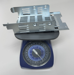
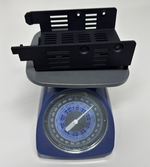
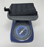
But that seems to boil down to PLA weighing more than PA12-HP Nylon. (I had the LED holder printed in PA11-HP.)

One thing I found out about the walled bracket is that it has the same flaw as Apple's bracket in that the holes don't fit common 3.5" hard drives like the Quantum shown below.
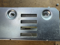
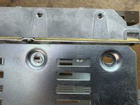
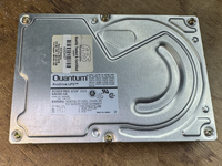
I had forgotten that I had to drill-out the holes on the stock SE/30 metal bracket in the past in order to make the Quantum drive be mountable.
Surely there must have been some ancient drives that Apple used as a reference HDD to choose the hole spacing in the first place. Even so, it would have been wiser of Apple to have made the holes OVAL shaped to accommodate drive hole spacing variations.
Here is how the 3D printed walled bracket looks with that Quantum drive...
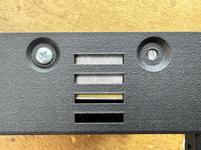
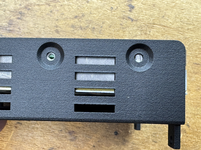
Rather surprisingly, I found that the 3D printed bracket included with MacSD (by @YMK ) seems to more closely match the Quantum drive hole spacing because that hole spacing too doesn't perfectly match the stock metal bracket or the walled bracket by @jmacz...
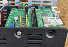
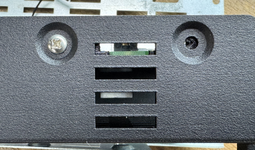
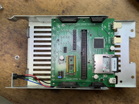
I am able to mount MacSD into the stock metal bracket only because I had drilled out the holes in the past to accommodate my Quantum drives...
The good news is that because I printed the plate, I can just use that instead for my MacSD, thereby solving that mounting hole spacing problem.
Solving it for a spinner drive though is hard because the holes are recessed into the plastic.
I'm glad I didn't print the 100% transparent version because drilling that out would ruin the aesthetics in the mounting hole area.
In regards to the plate, as I just said, the holes on the bottom of the MacSD bracket line up just fine, but the trouble is that in the normal/preferred mounting position with the SD card at the back, MacSD hangs off the back and now blocks the Main Wiring Harness connector in a manner similar to the stock metal bracket!
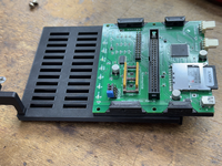
Flipping MacSD into the undesirable position of the SD card facing the front (which means the SCSI ribbon cable will awkwardly cover and block the LED wires, works to allow MacSD to sit squarely in the middle of the plate, which is better than hanging off the back...
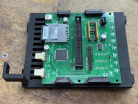
I am now thinking about drilling-out 2 holes in the plate, close to the front of the plate, as that would then allow MacSD to be mounted in the preferred position with the SD card facing toward the back, yet without it hanging off the back. Then again, if I use washers and nuts screwed down tightly, I might get enough mounting stability with just 2 bolts instead of all 4.
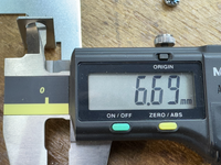
There is a difference between the stock metal bracket and the 3D bracket in terms of the diameter of the LED mounting hole. The 3D printed bracket's hole is just barely wide enough to slide in an LED. It isn't wide enough to accommodate the plastic mount used with vintage drive LEDs...
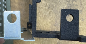
Stock metal bracket LED hole is about 6.7mm wide.
3D printed bracket's hole is about 5.15mm wide.
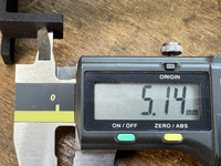
Vintage LED's have black plastic mounting hardware that necessitates the larger LED mounting hole.


However, the 3D bracket is plastic and therefore easier to drill.
This info applies to the LED mounting hole diameter on the Plate type as well. Both the Walled Bracket and Plate bracket seem to use the same LED hole diameter.
I will report back once I have made the required mods to at least mount my MacSD and its LED. The spinner drive will take more thought.
Thanks again to @jmacz for these 3D printable STL files!
My JLC3DP order arrived, and I've done some analysis.
First, while both plastic drive brackets are of course lighter in weight than the stock metal, it's interesting to see that the plate weighs almost as much as the walled bracket.


But that seems to boil down to PLA weighing more than PA12-HP Nylon. (I had the LED holder printed in PA11-HP.)
One thing I found out about the walled bracket is that it has the same flaw as Apple's bracket in that the holes don't fit common 3.5" hard drives like the Quantum shown below.


I had forgotten that I had to drill-out the holes on the stock SE/30 metal bracket in the past in order to make the Quantum drive be mountable.
Surely there must have been some ancient drives that Apple used as a reference HDD to choose the hole spacing in the first place. Even so, it would have been wiser of Apple to have made the holes OVAL shaped to accommodate drive hole spacing variations.
Here is how the 3D printed walled bracket looks with that Quantum drive...


Rather surprisingly, I found that the 3D printed bracket included with MacSD (by @YMK ) seems to more closely match the Quantum drive hole spacing because that hole spacing too doesn't perfectly match the stock metal bracket or the walled bracket by @jmacz...


I am able to mount MacSD into the stock metal bracket only because I had drilled out the holes in the past to accommodate my Quantum drives...

The good news is that because I printed the plate, I can just use that instead for my MacSD, thereby solving that mounting hole spacing problem.
Solving it for a spinner drive though is hard because the holes are recessed into the plastic.
I'm glad I didn't print the 100% transparent version because drilling that out would ruin the aesthetics in the mounting hole area.
In regards to the plate, as I just said, the holes on the bottom of the MacSD bracket line up just fine, but the trouble is that in the normal/preferred mounting position with the SD card at the back, MacSD hangs off the back and now blocks the Main Wiring Harness connector in a manner similar to the stock metal bracket!

Flipping MacSD into the undesirable position of the SD card facing the front (which means the SCSI ribbon cable will awkwardly cover and block the LED wires, works to allow MacSD to sit squarely in the middle of the plate, which is better than hanging off the back...

I am now thinking about drilling-out 2 holes in the plate, close to the front of the plate, as that would then allow MacSD to be mounted in the preferred position with the SD card facing toward the back, yet without it hanging off the back. Then again, if I use washers and nuts screwed down tightly, I might get enough mounting stability with just 2 bolts instead of all 4.
There is a difference between the stock metal bracket and the 3D bracket in terms of the diameter of the LED mounting hole. The 3D printed bracket's hole is just barely wide enough to slide in an LED. It isn't wide enough to accommodate the plastic mount used with vintage drive LEDs...

Stock metal bracket LED hole is about 6.7mm wide.

3D printed bracket's hole is about 5.15mm wide.

Vintage LED's have black plastic mounting hardware that necessitates the larger LED mounting hole.
However, the 3D bracket is plastic and therefore easier to drill.
This info applies to the LED mounting hole diameter on the Plate type as well. Both the Walled Bracket and Plate bracket seem to use the same LED hole diameter.
I will report back once I have made the required mods to at least mount my MacSD and its LED. The spinner drive will take more thought.
Thanks again to @jmacz for these 3D printable STL files!
One thing I found out about the walled bracket is that it has the same flaw as Apple's bracket in that the holes don't fit common 3.5" hard drives like the Quantum shown below.
Surely there must have been some ancient drives that Apple used as a reference HDD to choose the hole spacing in the first place. Even so, it would have been wiser of Apple to have made the holes OVAL shaped to accommodate drive hole spacing variations.
Oh interesting... The holes on both the walls of the walled model and the plate of the wall-less model are lined up the same, and both of them match the spacing on the stock metal HD bracket from the compact Macs (as you also saw). And they also lined up with the holes in the stock metal HD bracket for the IIci/IIcx/Quadra 700.
And the spinning hard disk I used to test the holes also aligned perfectly (and as such works perfectly with the stock metal bracket in the IIci as well as the compact mac bracket). This drive I used to test was a Quantum drive, a Quantum ProDrive (the super thick ones).
I just grabbed the newer thinner Quantum ProDrive and found they are different! On the thicker Quantum ProDrive, the bottom holes and the side holes are aligned the same and match the stock metal HD bracket. But on the newer thinner Quantum ProDrives, the bottom holes and the side holes do not match!! and thus the thinner Quantums won't work in the stock metal HD bracket from the compact Macs. Bizarre!
What I can do is put up a newer revision of the walled model that has an oval hole for the rear pair of holes so that it can work with both types of spinning disks. Will try to do this this weekend.
If you want to reuse the walled model you already printed, you should be able to enlarge the rear pair of holes by drilling new holes and then removing the remaining plastic between the holes to create an oval.
In regards to the plate, as I just said, the holes on the bottom of the MacSD bracket line up just fine, but the trouble is that in the normal/preferred mounting position with the SD card at the back, MacSD hangs off the back and now blocks the Main Wiring Harness connector in a manner similar to the stock metal bracket!
Sounds like the MacSD bracket matched the thinner quantum drives with the side holes and bottom holes not lined up with each other.
Just to understand, is it that the MacSD bracket sits too far back because the holes for the MacSD side mount and the holes on MacSD bottom are not at the same spot? They are further back?
You can try drilling new holes. Depending on how much infill the manufacturer used when printing it, it may or may not work. If there was a cavity where you drill, it might not work as well. You can always try.
What I can do for this model is put another set of four holes on the plate. But have them offset by some amount of millimeters. Just let me know how far towards the front the new set of holes need to be and I can put those in.
There is a difference between the stock metal bracket and the 3D bracket in terms of the diameter of the LED mounting hole. The 3D printed bracket's hole is just barely wide enough to slide in an LED. It isn't wide enough to accommodate the plastic mount used with vintage drive LEDs...
The models were designed to take the LED without the plastic bushing used in the stock metal bracket, because the models are already plastic. The stock setup used those plastic black bushings because the bracket was metal. I didn't think it made sense to make the hole larger to accommodate the bushing because some people might not have that bushing, or if they replaced the LED (the stock one burned out), they wouldn't have that bushing either.
You should be able to remove the stock LED from that bushing.
Or if you think people might want the larger hole and use the bushing, I can put up another revision of the model with a larger hole to accommodate the bushing. I won't be able to test it as I don't have an LED with that stock bushing but I can certainly make a variant with the measurements you took of the stock hole.
Saturday mornings (Japan time) are the only time I get a reasonable amount of sleep (8 hours). Now that I'm refreshed, I will share some photos I took last night.
But because the PLATE mount is made for MacSD and similar, and because the WALLED BRACKET is made for spinner drives, it's not really a problem to glue an LED down. I used BONDIC to glue my MacSD's multi-wire LED because you need the glue to solidify fast in order to secure the LED in the hole perfectly straight and all the way down in the hole. Hot Glue was a consideration, but it's messy and not precise like BONDIC. BONDIC cures in seconds with UV light, (especially with my UV flashlight that is 10W).
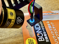
I had to order M3 bolts (aka "machine screws"), washers and nuts from Amazon last night, so I will take another photo when those arrive tomorrow, but for now, you can see how the PLATE bracket mounts atop the Floppy Drive in my SE/30...
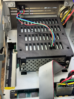
It's so lovely and wonderful without that horrid back part hanging off like the metal brackets!
Separately from that...
It's hard to photograph, but there is a little gap between the very tip of the protruding LED and the back of the transparent rectangular LED hole on the front of the SE/30's plastic case. And while the LED is not perfectly centered behind that rectangular hole on the 3D printed case, it isn't centered when using the metal mounting bracket either. The LED should be bright enough to where you wouldn't notice it being off-center when viewing the rectangular LED hole from the front of the computer. Being off-center is just a tiny detail I noticed and wanted to mention.
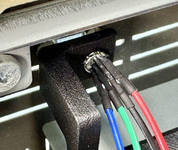
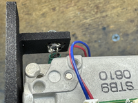
To address that problem, I started by putting a drill bit into the rear hole of the WALLED bracket. The bit's diameter was slightly smaller than the existing hole. I then aimed the front of the bracket straight down toward my desk, spun the drill, then pulled downward on the drill with the aim of creating an elongated "oval" shaped hole to accommodate the bolt spacing of any 3.5" drive. Turns out though that drilling PA12-HP Nylon in the way I did is nice in concept, but after several minutes I really wasn't making progress.
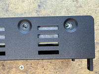
I then whipped out my X-acto knife and what do you know, it made quick work of cutting through the Nylon! The only issue is the "recessed" part of the case isn't easy to reproduce by hand. The photo below shows the work of my knife, without any expansion of the surrounding recessed part.
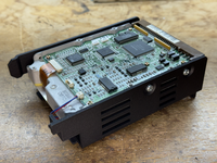
After that, I did a little more whittling on the leftmost edge of the recessed part in order to allow the left side of my mounting bolt to go down better. I didn't fully get the recessed part cut out to my satisfaction, but this bracket is plastic, so I was hoping that if I screwed down the bolt hard enough, it would just sink-in. It did sink in a little bit, and the rear bolt seems to be secure, as shown below.
If the STL for the WALLED bracket could be modified to elongate the hole (elongated it toward front of the case), then it could accommodate all compatible 3.5" drives. Height of that hole need not be changed, only the width.
But when I removed the bracket fresh out of the JLC3DP box, I noticed the two walls were not perfectly perpendicular to ground level. That's no big deal because you will bolt to the sides to a hard drive, and that will make the two walls then be perfectly perpendicular.
However, that only works perfectly when there are sufficient bolts, and right now, there are only 2 bolt holes on each wall. There is no hole toward the front where the LED is.
The lack of a hole (and bolt) close to the LED means there is a small gap between the wall in that area and the drive body, as you can see in the photo below. The rightmost wall is very slightly bowing outward, away from the drive body.
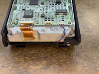
And in the following two photos, you can see the bowing more clearly when I am not pressing against it, and then when I press inward (toward the drive) with my finger.
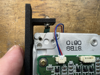
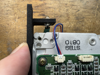
The solution to this problem would be to simply to add a 3rd bolt hole in each wall (requiring a mod to the STL file), because the Quantum LPS drive you see in my photos has 3 holes on both sides.
Of course, making the LED side of the wall be perfectly perpendicular with the addition of a 3rd bolt hole would mean that the LED is moved even more to the right, making it even more off center from that rectangular hole in the front plastic case, but it would be no different than when using the metal mounting bracket. Not a big deal. Just an observation.
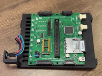
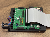
But look at the ONLY orientation BlueSCSI allows...
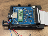
DISCLAIMER: My factual observations must NEVER to be misinterpreted as me being against BlueSCSI. I am not against BlueSCSI. I am merely stating facts about mounting orientation to educate and inform the reader about mounting with this particular 3D printed PLATE.
As you can see in the above photo of BlueSCSIv2, the SD card is located near the LED, which is right behind the front plastic of the SE or SE/30, making it absolutely IMPOSSIBLE to remove the SD card once the BSv2 is mounted to the plate! And since you cannot mount BSv2 further back because the overhang would cover the Main Wiring Harness Connector, the only way BSv2 could be used is if you buy an SD card EXTENDER and then run that ribbon cable to the rear housing's Expansion Slot. Some people do that, although the SD Extenders I own don't fit any known 3D-printable Rear Expansion Slot Brackets...
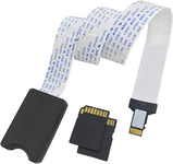
If anyone knows of a 3D printable Expansion Slot bracket that accommodates that exact SD Card Extender, please let me know.
But even though BSv2 cannot be used on the PLATE bracket without using some kind of SD card EXTENDER, the plate is perfect for MacSD, and maybe for other SD card type drives too which I personally don't own. But if there could be a pair of holes made in the PLATE's STL file, that would then allow MacSD owners the option of using 4 bolts rather than 2.
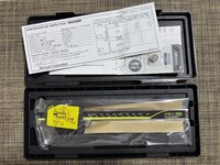
Sadly, I left my calipers at the office YET AGAIN, so I cannot measure today. I do that all the time and it drives me nuts! So last night I solved that problem once and for all by ordering the Mitutoyo CD-15AX (expensive, but with great battery life and 2 decimal points of metric precision). One at home and one at the office will ensure I always have the ability to measure precisely!
My Amazon order won't be delivered until tomorrow, so I hope to reply back at that time with some final photos showing the bolts and washers and nuts I ordered, having everything fully mounted inside the SE/30.
LED MOUNTING [ PLATE BRACKET ]
As per the conversation we had yesterday, I did not use the vintage black-plastic LED mount (which requires a larger hole in the bracket). I instead just glued the bare naked LED into the hole. The downside of gluing is you really absolutely MUST to make a final decision about what LED you use there, be that a 2-wire LED for a spinner drive, or a multi-wire LED for a MacSD.But because the PLATE mount is made for MacSD and similar, and because the WALLED BRACKET is made for spinner drives, it's not really a problem to glue an LED down. I used BONDIC to glue my MacSD's multi-wire LED because you need the glue to solidify fast in order to secure the LED in the hole perfectly straight and all the way down in the hole. Hot Glue was a consideration, but it's messy and not precise like BONDIC. BONDIC cures in seconds with UV light, (especially with my UV flashlight that is 10W).

I had to order M3 bolts (aka "machine screws"), washers and nuts from Amazon last night, so I will take another photo when those arrive tomorrow, but for now, you can see how the PLATE bracket mounts atop the Floppy Drive in my SE/30...

It's so lovely and wonderful without that horrid back part hanging off like the metal brackets!
Separately from that...
It's hard to photograph, but there is a little gap between the very tip of the protruding LED and the back of the transparent rectangular LED hole on the front of the SE/30's plastic case. And while the LED is not perfectly centered behind that rectangular hole on the 3D printed case, it isn't centered when using the metal mounting bracket either. The LED should be bright enough to where you wouldn't notice it being off-center when viewing the rectangular LED hole from the front of the computer. Being off-center is just a tiny detail I noticed and wanted to mention.

LED MOUNTING [ WALLED BRACKET ]
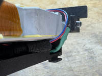
I also used BONDIC to glue a 2-wire LED to the LED hole of the walled bracket, which is used by a spinning platter HDD. Due to the extra thickness (versus the stock metal bracket), the back side of your LED will come much closer to the hard drive body, creating the need for you to bend the two LED wires downward in a more abrupt manner. As shown below, it does barely fit when you do that. Just make sure your LED wires are insulated because the body of a hard drive is metal.

CUTTING AN OVAL & MOUNTING A QUANTUM "LPS" DRIVE [ WALLED BRACKET ]
As mentioned in our dialog yesterday, the hole spacing on the sides of certain 3.5" spinning platter hard drives vary. So having fixed spacing for round holes in the current version STL file is problematic, just as it is for the stock metal bracket from Apple.To address that problem, I started by putting a drill bit into the rear hole of the WALLED bracket. The bit's diameter was slightly smaller than the existing hole. I then aimed the front of the bracket straight down toward my desk, spun the drill, then pulled downward on the drill with the aim of creating an elongated "oval" shaped hole to accommodate the bolt spacing of any 3.5" drive. Turns out though that drilling PA12-HP Nylon in the way I did is nice in concept, but after several minutes I really wasn't making progress.
I then whipped out my X-acto knife and what do you know, it made quick work of cutting through the Nylon! The only issue is the "recessed" part of the case isn't easy to reproduce by hand. The photo below shows the work of my knife, without any expansion of the surrounding recessed part.

After that, I did a little more whittling on the leftmost edge of the recessed part in order to allow the left side of my mounting bolt to go down better. I didn't fully get the recessed part cut out to my satisfaction, but this bracket is plastic, so I was hoping that if I screwed down the bolt hard enough, it would just sink-in. It did sink in a little bit, and the rear bolt seems to be secure, as shown below.

If the STL for the WALLED bracket could be modified to elongate the hole (elongated it toward front of the case), then it could accommodate all compatible 3.5" drives. Height of that hole need not be changed, only the width.
ADD A 3RD HOLE ON BOTH WALLS?
One thing I noticed about this PA12-HP Nylon is that it is not as firm as PLA or PA12-CF (carbon fiber). It's quite firm, but not as firm as a rock. The walls will bend in and out when you apply sufficient finger pressure. It's not as much as TPU, but it is a Nylon plastic and has a little give. I see that as a good thing, actually, because I think it provides more vibration damping for the attached drive.But when I removed the bracket fresh out of the JLC3DP box, I noticed the two walls were not perfectly perpendicular to ground level. That's no big deal because you will bolt to the sides to a hard drive, and that will make the two walls then be perfectly perpendicular.
However, that only works perfectly when there are sufficient bolts, and right now, there are only 2 bolt holes on each wall. There is no hole toward the front where the LED is.
The lack of a hole (and bolt) close to the LED means there is a small gap between the wall in that area and the drive body, as you can see in the photo below. The rightmost wall is very slightly bowing outward, away from the drive body.

And in the following two photos, you can see the bowing more clearly when I am not pressing against it, and then when I press inward (toward the drive) with my finger.


The solution to this problem would be to simply to add a 3rd bolt hole in each wall (requiring a mod to the STL file), because the Quantum LPS drive you see in my photos has 3 holes on both sides.
Of course, making the LED side of the wall be perfectly perpendicular with the addition of a 3rd bolt hole would mean that the LED is moved even more to the right, making it even more off center from that rectangular hole in the front plastic case, but it would be no different than when using the metal mounting bracket. Not a big deal. Just an observation.
BLUESCSI v2 MOUNTING ISSUE [ PLATE BRACKET ]
MacSD's included plastic bracket is better suited for use on the PLATE BRACKET than BlueSCSIv2 plastic bracket. Of course, BlueSCSIv2 bracket has the same fundamental problem as MacSD's bracket in that one particular orientation would make either drive hang off the back of the bracket. That is bad because that "hanging off" orientation would cover the motherboard's main wiring harness connector. But the other orientation for MacSD is perfect, keeping the drive centered on the PLATE bracket, while also keeping the SD card in the back, and allowing the ribbon cable to come nicely off in back too, while keeping your LED connections in front. It's just all around good — except for the lack of holes in the front of the PLATE bracket, which means you must either use 2 bolts only to mount MacSD to the PLATE bracket, or drill out two more holes in the front of the PLATE so you can use 4 bolts total...

But look at the ONLY orientation BlueSCSI allows...

DISCLAIMER: My factual observations must NEVER to be misinterpreted as me being against BlueSCSI. I am not against BlueSCSI. I am merely stating facts about mounting orientation to educate and inform the reader about mounting with this particular 3D printed PLATE.
As you can see in the above photo of BlueSCSIv2, the SD card is located near the LED, which is right behind the front plastic of the SE or SE/30, making it absolutely IMPOSSIBLE to remove the SD card once the BSv2 is mounted to the plate! And since you cannot mount BSv2 further back because the overhang would cover the Main Wiring Harness Connector, the only way BSv2 could be used is if you buy an SD card EXTENDER and then run that ribbon cable to the rear housing's Expansion Slot. Some people do that, although the SD Extenders I own don't fit any known 3D-printable Rear Expansion Slot Brackets...

If anyone knows of a 3D printable Expansion Slot bracket that accommodates that exact SD Card Extender, please let me know.
But even though BSv2 cannot be used on the PLATE bracket without using some kind of SD card EXTENDER, the plate is perfect for MacSD, and maybe for other SD card type drives too which I personally don't own. But if there could be a pair of holes made in the PLATE's STL file, that would then allow MacSD owners the option of using 4 bolts rather than 2.
Sadly, I left my calipers at the office YET AGAIN, so I cannot measure today. I do that all the time and it drives me nuts! So last night I solved that problem once and for all by ordering the Mitutoyo CD-15AX (expensive, but with great battery life and 2 decimal points of metric precision). One at home and one at the office will ensure I always have the ability to measure precisely!
My Amazon order won't be delivered until tomorrow, so I hope to reply back at that time with some final photos showing the bolts and washers and nuts I ordered, having everything fully mounted inside the SE/30.
As per the conversation we had yesterday, I did not use the vintage black-plastic LED mount (which requires a larger hole in the bracket). I instead just glued the bare naked LED into the hole. The downside of gluing is you really absolutely MUST to make a final decision about what LED you use there, be that a 2-wire LED for a spinner drive, or a multi-wire LED for a MacSD.
I prefer using hot glue. It dries quick and is easily reversible.
And while the LED is not perfectly centered behind that rectangular hole on the 3D printed case, it isn't centered when using the metal mounting bracket either. The LED should be bright enough to where you wouldn't notice it being off-center when viewing the rectangular LED hole from the front of the computer. Being off-center is just a tiny detail I noticed and wanted to mention.
Yes, the measurements were taken off the stock metal bracket and hence the LED is in the same position as the stock bracket, which is slightly offset. All the compact Macs I have owned had that slight offset so I was never sure if that was Apple's intent? I can shift the hole if you think that makes sense, just let me know how many millimeters to shift it by and in which direction.
If the STL for the WALLED bracket could be modified to elongate the hole (elongated it toward front of the case), then it could accommodate all compatible 3.5" drives. Height of that hole need not be changed, only the width.
Yeah per my previous reply, I can extend the rear holes to be ovals. I will make that revision.
The solution to this problem would be to simply to add a 3rd bolt hole in each wall (requiring a mod to the STL file), because the Quantum LPS drive you see in my photos has 3 holes on both sides.
I will need to see if I have a drive with a third hole on the side. If so, I can make this change as well.
But when I removed the bracket fresh out of the JLC3DP box, I noticed the two walls were not perfectly perpendicular to ground level.
This might be due to whatever the printer did. On mine, the walls are perfectly vertical / perpendicular to the ground level.
But if there could be a pair of holes made in the PLATE's STL file, that would then allow MacSD owners the option of using 4 bolts rather than 2.
Yeah per my previous reply, there are four holes right now, and you had mentioned those stock hole positions are too far back towards the rear causing the MacSD to hang off the plate. I can add four more holes closer to the front of the plate to provide more mounting options. Just let me know how far forward you want the second set of four holes to be from the current set.
Sadly, I left my calipers at the office YET AGAIN, so I cannot measure today. I do that all the time and it drives me nuts! So last night I solved that problem once and for all by ordering the Mitutoyo CD-15AX (expensive, but with great battery life and 2 decimal points of metric precision). One at home and one at the office will ensure I always have the ability to measure precisely!
Good choice. I also use Mitutoyos.
@JDW I need two measurements:
1.) For the additional four holes on the wall-less model, how far forward you want them compared to the existing four holes.
2.) (Optional) If you want me to move the LED hole a little bit to center it in the front case opening, let me know how far to shift (in MM) and in which direction.
I have added the oval shaped hole to accommodate newer Quantum drives, and also added the third hole in the wall for the same newer Quantum drives.

I have also prepped the wall-less model with the additional set of holes. I just need the measurement on how far forward to place them.

1.) For the additional four holes on the wall-less model, how far forward you want them compared to the existing four holes.
2.) (Optional) If you want me to move the LED hole a little bit to center it in the front case opening, let me know how far to shift (in MM) and in which direction.
I have added the oval shaped hole to accommodate newer Quantum drives, and also added the third hole in the wall for the same newer Quantum drives.
I have also prepped the wall-less model with the additional set of holes. I just need the measurement on how far forward to place them.
Last edited:
Hi @JDW,Saturday mornings (Japan time) are the only time I get a reasonable amount of sleep (8 hours). Now that I'm refreshed, I will share some photos I took last night.
LED MOUNTING [ PLATE BRACKET ]
As per the conversation we had yesterday, I did not use the vintage black-plastic LED mount (which requires a larger hole in the bracket). I instead just glued the bare naked LED into the hole. The downside of gluing is you really absolutely MUST to make a final decision about what LED you use there, be that a 2-wire LED for a spinner drive, or a multi-wire LED for a MacSD.
But because the PLATE mount is made for MacSD and similar, and because the WALLED BRACKET is made for spinner drives, it's not really a problem to glue an LED down. I used BONDIC to glue my MacSD's multi-wire LED because you need the glue to solidify fast in order to secure the LED in the hole perfectly straight and all the way down in the hole. Hot Glue was a consideration, but it's messy and not precise like BONDIC. BONDIC cures in seconds with UV light, (especially with my UV flashlight that is 10W).
View attachment 23938
I had to order M3 bolts (aka "machine screws"), washers and nuts from Amazon last night, so I will take another photo when those arrive tomorrow, but for now, you can see how the PLATE bracket mounts atop the Floppy Drive in my SE/30...
View attachment 23942
It's so lovely and wonderful without that horrid back part hanging off like the metal brackets!
Separately from that...
It's hard to photograph, but there is a little gap between the very tip of the protruding LED and the back of the transparent rectangular LED hole on the front of the SE/30's plastic case. And while the LED is not perfectly centered behind that rectangular hole on the 3D printed case, it isn't centered when using the metal mounting bracket either. The LED should be bright enough to where you wouldn't notice it being off-center when viewing the rectangular LED hole from the front of the computer. Being off-center is just a tiny detail I noticed and wanted to mention.
View attachment 23940
LED MOUNTING [ WALLED BRACKET ]
I also used BONDIC to glue a 2-wire LED to the LED hole of the walled bracket, which is used by a spinning platter HDD. Due to the extra thickness (versus the stock metal bracket), the back side of your LED will come much closer to the hard drive body, creating the need for you to bend the two LED wires downward in a more abrupt manner. As shown below, it does barely fit when you do that. Just make sure your LED wires are insulated because the body of a hard drive is metal.
View attachment 23943 View attachment 23944
CUTTING AN OVAL & MOUNTING A QUANTUM "LPS" DRIVE [ WALLED BRACKET ]
As mentioned in our dialog yesterday, the hole spacing on the sides of certain 3.5" spinning platter hard drives vary. So having fixed spacing for round holes in the current version STL file is problematic, just as it is for the stock metal bracket from Apple.
To address that problem, I started by putting a drill bit into the rear hole of the WALLED bracket. The bit's diameter was slightly smaller than the existing hole. I then aimed the front of the bracket straight down toward my desk, spun the drill, then pulled downward on the drill with the aim of creating an elongated "oval" shaped hole to accommodate the bolt spacing of any 3.5" drive. Turns out though that drilling PA12-HP Nylon in the way I did is nice in concept, but after several minutes I really wasn't making progress.
I then whipped out my X-acto knife and what do you know, it made quick work of cutting through the Nylon! The only issue is the "recessed" part of the case isn't easy to reproduce by hand. The photo below shows the work of my knife, without any expansion of the surrounding recessed part.
View attachment 23945
After that, I did a little more whittling on the leftmost edge of the recessed part in order to allow the left side of my mounting bolt to go down better. I didn't fully get the recessed part cut out to my satisfaction, but this bracket is plastic, so I was hoping that if I screwed down the bolt hard enough, it would just sink-in. It did sink in a little bit, and the rear bolt seems to be secure, as shown below.
View attachment 23946
If the STL for the WALLED bracket could be modified to elongate the hole (elongated it toward front of the case), then it could accommodate all compatible 3.5" drives. Height of that hole need not be changed, only the width.
ADD A 3RD HOLE ON BOTH WALLS?
One thing I noticed about this PA12-HP Nylon is that it is not as firm as PLA or PA12-CF (carbon fiber). It's quite firm, but not as firm as a rock. The walls will bend in and out when you apply sufficient finger pressure. It's not as much as TPU, but it is a Nylon plastic and has a little give. I see that as a good thing, actually, because I think it provides more vibration damping for the attached drive.
But when I removed the bracket fresh out of the JLC3DP box, I noticed the two walls were not perfectly perpendicular to ground level. That's no big deal because you will bolt to the sides to a hard drive, and that will make the two walls then be perfectly perpendicular.
However, that only works perfectly when there are sufficient bolts, and right now, there are only 2 bolt holes on each wall. There is no hole toward the front where the LED is.
The lack of a hole (and bolt) close to the LED means there is a small gap between the wall in that area and the drive body, as you can see in the photo below. The rightmost wall is very slightly bowing outward, away from the drive body.
View attachment 23947
And in the following two photos, you can see the bowing more clearly when I am not pressing against it, and then when I press inward (toward the drive) with my finger.
View attachment 23949 View attachment 23948
The solution to this problem would be to simply to add a 3rd bolt hole in each wall (requiring a mod to the STL file), because the Quantum LPS drive you see in my photos has 3 holes on both sides.
Of course, making the LED side of the wall be perfectly perpendicular with the addition of a 3rd bolt hole would mean that the LED is moved even more to the right, making it even more off center from that rectangular hole in the front plastic case, but it would be no different than when using the metal mounting bracket. Not a big deal. Just an observation.
BLUESCSI v2 MOUNTING ISSUE [ PLATE BRACKET ]
MacSD's included plastic bracket is better suited for use on the PLATE BRACKET than BlueSCSIv2 plastic bracket. Of course, BlueSCSIv2 bracket has the same fundamental problem as MacSD's bracket in that one particular orientation would make either drive hang off the back of the bracket. That is bad because that "hanging off" orientation would cover the motherboard's main wiring harness connector. But the other orientation for MacSD is perfect, keeping the drive centered on the PLATE bracket, while also keeping the SD card in the back, and allowing the ribbon cable to come nicely off in back too, while keeping your LED connections in front. It's just all around good — except for the lack of holes in the front of the PLATE bracket, which means you must either use 2 bolts only to mount MacSD to the PLATE bracket, or drill out two more holes in the front of the PLATE so you can use 4 bolts total...
View attachment 23951 View attachment 23950
But look at the ONLY orientation BlueSCSI allows...
View attachment 23952
DISCLAIMER: My factual observations must NEVER to be misinterpreted as me being against BlueSCSI. I am not against BlueSCSI. I am merely stating facts about mounting orientation to educate and inform the reader about mounting with this particular 3D printed PLATE.
As you can see in the above photo of BlueSCSIv2, the SD card is located near the LED, which is right behind the front plastic of the SE or SE/30, making it absolutely IMPOSSIBLE to remove the SD card once the BSv2 is mounted to the plate! And since you cannot mount BSv2 further back because the overhang would cover the Main Wiring Harness Connector, the only way BSv2 could be used is if you buy an SD card EXTENDER and then run that ribbon cable to the rear housing's Expansion Slot. Some people do that, although the SD Extenders I own don't fit any known 3D-printable Rear Expansion Slot Brackets...
View attachment 23953
If anyone knows of a 3D printable Expansion Slot bracket that accommodates that exact SD Card Extender, please let me know.
But even though BSv2 cannot be used on the PLATE bracket without using some kind of SD card EXTENDER, the plate is perfect for MacSD, and maybe for other SD card type drives too which I personally don't own. But if there could be a pair of holes made in the PLATE's STL file, that would then allow MacSD owners the option of using 4 bolts rather than 2.
Sadly, I left my calipers at the office YET AGAIN, so I cannot measure today. I do that all the time and it drives me nuts! So last night I solved that problem once and for all by ordering the Mitutoyo CD-15AX (expensive, but with great battery life and 2 decimal points of metric precision). One at home and one at the office will ensure I always have the ability to measure precisely!
My Amazon order won't be delivered until tomorrow, so I hope to reply back at that time with some final photos showing the bolts and washers and nuts I ordered, having everything fully mounted inside the SE/30.
I had left you a reply on on another thread about the item you are looking for. I believe this will fit the bill. It is the second variant STL listed. The author listed what card reader extension to use and it the one you are trying to use:
https://www.printables.com/model/572256-macintosh-se-se30-expansion-slot-option-panels
I haven't had luck with those card extensions, at least various ones available on Amazon. A lot of them seem to be slightly off in dimensions resulting in less than 100% reliability making contact, either on the side that inserts into your device or on the side that you insert your SD card into. The result being random unpredictable glitches during IO. I had random crashes, read/write errors, boot errors, etc on my fleet of Macs until I removed them. Ended up deleting and reinstalling clean images on all my SD cards as I saw some evidence of corrupted files. Reproduced on modern machines as well with the same extensions. So I gave up.
Thank for that info.! I will give you a follow up shortly..... stay tunedI haven't had luck with those card extensions, at least various ones available on Amazon. A lot of them seem to be slightly off in dimensions resulting in less than 100% reliability making contact, either on the side that inserts into your device or on the side that you insert your SD card into. The result being random unpredictable glitches during IO. I had random crashes, read/write errors, boot errors, etc on my fleet of Macs until I removed them. Ended up deleting and reinstalling clean images on all my SD cards as I saw some evidence of corrupted files. Reproduced on modern machines as well with the same extensions. So I gave up.
Regarding the LED being slightly off-center (to the right), relative to that rectangular window hole on the front plastic case of the SE or SE/30 (when viewed from the back of the machine (with rear housing removed, of course)...
I am seeing that rectangle to be pretty much right at 8.0mm wide.
It seems that the rightmost edge of the LED is about where the rightmost edge of that rectangle is (with LED installed, and PLATE Bracked mounted atop Floppy Drive). LED diameter is 5mm, so (8 - 5) / 2 = 1.5mm (the amount of shift-to-the-left required for the LED hole).
In terms of the HOLES in the PLATE bracket...
I have measured MacSD as follows:
PLASTIC BRACKET INCLUDED WITH MACSD
Distance from outer edges of each hole: 48.45mm
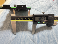
But that is a PLA printed bracket, which wouldn't give the most accurate measurements, so I measured the holes in the PCB, which sit directly above the holes in the PLA bracket. Distance to outer edges of the two holes: 47.80mm.
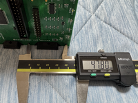
Distance from the inner edges of the two holes: 41.43mm
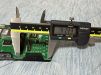
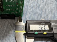
Diameter of one hole: 3.2mm
There are only 4 holes total on MacSD,and because the spacing doesn't match the PLATE bracket version that I printed, and because I needed to flip MacSD 180° to keep it centered on the PLATE bracket, I used only 2 bolts to mount it as shown below...
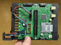
Those two bolts alone are holding it down well, such that I cannot move it around when I press against it or try to twist it. That may be enough, actually.
Nevertheless, if two more holes in the plate were added, it would give people the option to use 4 bolts if they want to.
I will reply about the walled bracket separately.
I am seeing that rectangle to be pretty much right at 8.0mm wide.
It seems that the rightmost edge of the LED is about where the rightmost edge of that rectangle is (with LED installed, and PLATE Bracked mounted atop Floppy Drive). LED diameter is 5mm, so (8 - 5) / 2 = 1.5mm (the amount of shift-to-the-left required for the LED hole).
In terms of the HOLES in the PLATE bracket...
I have measured MacSD as follows:
PLASTIC BRACKET INCLUDED WITH MACSD
Distance from outer edges of each hole: 48.45mm

But that is a PLA printed bracket, which wouldn't give the most accurate measurements, so I measured the holes in the PCB, which sit directly above the holes in the PLA bracket. Distance to outer edges of the two holes: 47.80mm.

Distance from the inner edges of the two holes: 41.43mm

Diameter of one hole: 3.2mm

There are only 4 holes total on MacSD,


Those two bolts alone are holding it down well, such that I cannot move it around when I press against it or try to twist it. That may be enough, actually.
Nevertheless, if two more holes in the plate were added, it would give people the option to use 4 bolts if they want to.
I will reply about the walled bracket separately.
Last edited:
Regarding the WALLED bracket...
I only have the small Quantum ProDrive LPS units which don't fit even the stock metal brackets perfectly, and that is why you added the oval cut-out on the back hole in your latest revision. There are 3 holes on each side of my quantum drive, and here are the measurements:
Quantum LPS HDD Hole diameter: 2.70mm
BACK 2 HOLES (toward the SCSI Ribbon Cable)
Distance between outer edges: 44.50mm
Distance between inner edges: 39.00mm
FRONT 2 HOLES
Distance between outer edges: 62.70mm
Distance between inner edges: 57.60mm
Subtracting the inner from the outer should yield the hole diameter, but it doesn't. Even so, your holes on each wall are about 4.3mm in diameter, which should give sufficient wiggle room. The main issue before the ovals were created was the rearmost hole was placed to match a different kind of drive. And on that topic, since I don't have that kind of drive, it would be best if you could test that, because I think you said you have one of those.
As you can see in the above photo of BlueSCSIv2, the SD card is located near the LED, which is right behind the front plastic of the SE or SE/30, making it absolutely IMPOSSIBLE to remove the SD card once the BSv2 is
If anyone knows of a 3D printable Expansion Slot bracket that accommodates that exact SD Card Extender, please let me know.
Hi @JDW ,
Consider yourself notified! Here is remix of a design that I had previously shown. I used the idea I had from another remix I did that caught your eye. This was printed with clear PETG:
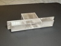
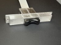
Unfortunately, I do not have an SE or SE/30 to test (yet
I am also making a variant that supports connecting a video out cable connector at the same time…
Wow. Great job!
I have the LCD color kit by ZZJ installed in my SE/30 and it has a video out connector, so your forthcoming video out connector version would be quite useful actually. I see uses for both of your versions.

