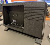
Made some more progress on the case. I think I'm going to try to make two case fronts, one for the iPad screen and one for the 11.6" screen. It should give flexibility.
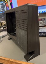
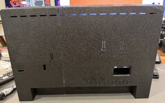
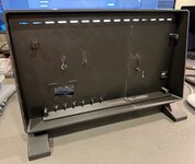
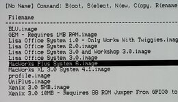
I also posted about this on the main LisaFPGA thread, but I added the ability to control the output resolution at runtime by adding a special on screen menu accessible by long pressing the SEL button. it also gives the ability to adjust the picture location within the LCD, so hopefully it will help with getting it perfectly centered in the screen.
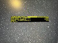
Still need to get the screen mounting figured out. The 11.6" screen may post some challenges due to size limits. But I think I can make it work hopefully by overlapping the LCD and the controller board by using longer standoffs for the controller so it can sit on a different plane than the LCD, easing getting things plugged in and avoiding interfering with each other.
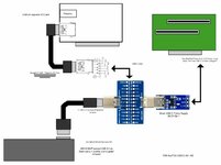
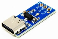
For power, my goal is one USB-C input to power everything. I have found a nice nook for a USB-C trigger board that will serve as power for the thing. The 11.6 screen uses 5v to power it, as does the LisaFPGA, so I will have the trigger board get 5v, and then split that 5v to the screen and the computer. The iPad screen will require a buck converter because the iPad screen controller uses 12v, so I'll set the trigger board to 12v, run one line to the LCD, then another 12v line will go to a buck converter dropping that to 5v for the LisaFPGA (or Raspberry Pi). Hopefully this will allow everything to run off one USB-C power supply.
I also posted about this on the main LisaFPGA thread, but I added the ability to control the output resolution at runtime by adding a special on screen menu accessible by long pressing the SEL button. it also gives the ability to adjust the picture location within the LCD, so hopefully it will help with getting it perfectly centered in the screen.
Still need to get the screen mounting figured out. The 11.6" screen may post some challenges due to size limits. But I think I can make it work hopefully by overlapping the LCD and the controller board by using longer standoffs for the controller so it can sit on a different plane than the LCD, easing getting things plugged in and avoiding interfering with each other.
For power, my goal is one USB-C input to power everything. I have found a nice nook for a USB-C trigger board that will serve as power for the thing. The 11.6 screen uses 5v to power it, as does the LisaFPGA, so I will have the trigger board get 5v, and then split that 5v to the screen and the computer. The iPad screen will require a buck converter because the iPad screen controller uses 12v, so I'll set the trigger board to 12v, run one line to the LCD, then another 12v line will go to a buck converter dropping that to 5v for the LisaFPGA (or Raspberry Pi). Hopefully this will allow everything to run off one USB-C power supply.