Apple Lisa 3d Case Project

wottle

Active Tinkerer
Oct 30, 2021
927
667
93
49
Fort Mill, SC
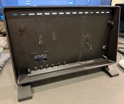
Made some more progress on the case. I think I'm going to try to make two case fronts, one for the iPad screen and one for the 11.6" screen. It should give flexibility.
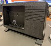
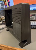
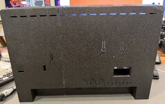
IMG_9578.jpeg IMG_9579.jpeg IMG_9580.jpeg IMG_9576.jpeg

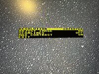
I also posted about this on the main LisaFPGA thread, but I added the ability to control the output resolution at runtime by adding a special on screen menu accessible by long pressing the SEL button. it also gives the ability to adjust the picture location within the LCD, so hopefully it will help with getting it perfectly centered in the screen.
IMG_9422.jpeg

Still need to get the screen mounting figured out. The 11.6" screen may post some challenges due to size limits. But I think I can make it work hopefully by overlapping the LCD and the controller board by using longer standoffs for the controller so it can sit on a different plane than the LCD, easing getting things plugged in and avoiding interfering with each other.

For power, my goal is one USB-C input to power everything. I have found a nice nook for a USB-C trigger board that will serve as power for the thing. The 11.6 screen uses 5v to power it, as does the LisaFPGA, so I will have the trigger board get 5v, and then split that 5v to the screen and the computer. The iPad screen will require a buck converter because the iPad screen controller uses 12v, so I'll set the trigger board to 12v, run one line to the LCD, then another 12v line will go to a buck converter dropping that to 5v for the LisaFPGA (or Raspberry Pi). Hopefully this will allow everything to run off one USB-C power supply.
 

wottle

Active Tinkerer
Oct 30, 2021
927
667
93
49
Fort Mill, SC
OK, I pretty much have the case design finished, with versions of the front piece for either an iPad 1024x768 LCD or the 11.6" widescreen 1080p LCD. And versions of the back case for either a LisaFPGA or a Raspberry Pi 4. I struggled a bit with my above mentioned LCD location adjustment functionality on the LisaFPGA, specifically getting it to save and persist the location between power cycles. But it is now working, and supports all three possible resolutions 1024x768@65Hz, 1080p30, and 1080p60.

I also had all my components set to install and power it all off of one USB-C input and ran into an issue. The USB-C male pigtail cables I was planning on using apparently are meant for pulling power from a USB-C device, not providing power to it. I should have realized this, since USB-C PD isn't a passive connection and simply providing 5v on the power line isn't all that's needed. I simply thought the 5V USB-C pigtails had the necessary resistors to negotiate that the cable would be supplying 5v. Apparently it is negotiating that it will pull 5v. And that causes my LCD controller board to do some weird things.

So, I'm looking into two options. One is to find the 5v line on the LCD and try to bypass the USB-C connection and supply the 5v line directly.
I'd prefer to avoid soldering if possible as it will make it easier for others to create their own if I can avoid it.

The other is to get a big USB-C male breakout board and add the resistor to make it act as a 5v supplier of power.

1786731293681.png


The third possibility is to have two USB-C ports on the back, one to power the LisaFPGA, and the other to power the LCD. The problem is I really don't have any room for a USB-C board in the port cutout area. the space is almost completely used up by the LisaFPGA board and ports, or the area with buttons. I could enlarge the back cutout, but it would mess up the symmetry with the feet. Not a big problem, but also not ideal.

Has anyone tried to power multiple USB-C devices with similar voltage like this on a project. Any good solutions? I suppose I could go with a 12v barrel jack and try to use a buck converter, but it really feels like maybe there's just a problem with powering both the LisaFPGA and the LCD off the same power supply...

IMG_0214.jpeg


Here's a video of it in action:
 

wottle

Active Tinkerer
Oct 30, 2021
927
667
93
49
Fort Mill, SC
Very, very cool! How did you implement the display's active area shifting?
I wish I could take credit. I have zero experience programming hardware via FPGA. I used Claude and guided it to update the HDMI output. Basically the Lisa emulation portion is outputting the standard resolution (depending on the ROM) and I just adjust the HDMI output to shift the output of that onto the 1920x1080 or 1024x768 canvas. I didn't realize it, and I still don't understand the whole details, but one big challenge was getting it to support all 3 resolution / refresh rates in a single deploy. The other challenge, which took way longer than getting the resolutions and adjustments to work, was getting it to be able to persist the setting between boots.
 
  • Like
Reactions: Paolo B

wottle

Active Tinkerer
Oct 30, 2021
927
667
93
49
Fort Mill, SC
Y’all are probably already tracking this, but a YouTuber did a related case (
) and it’s available for preorder at https://jcm-1.com/product/lisafpga-3d-printed-case/.

Not as cool as having one with a monitor of course!
Yeah, that’s way better than mine! I like the light pipes, so I might need to see if I can print those and incorporate it into the back of mine.

Work has been crazy lately, so I haven’t had time to resume work on this, but I did pick up a K2 Plus printer which can print the case in one piece. Still dialing in the printer before I put my platinum PLA in there. The main thing I need to figure out is how to power the LCD and the LisaFPGA off a single USB-c power source.
 
  • Like
Reactions: srudolph

Trash80toG4

Active Tinkerer
Apr 1, 2022
1,459
465
83
Bermuda Triangle, NC USA
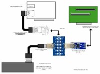
I was playing around with a USB-C AUX Power Supply that handles Data/HID on the single line.
Dunno if it'll help, but here's what I cobbled together:

TAM-AuxPSU-USB-C-001.jpg


1787772099474.jpeg

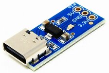
The AK-USBSUPPLY-C board takes power from an external power supply through a USB type C cable and delivers 3.3V and 5V through two dedicated pins. You can use this board to supply 5V and 3.3V to other peripherals and boards by using a standard wall charger, USB hub or a PC USB port.
 

Attachments

  • TAM-AuxPSU-USB-C-001.pdf
    415.3 KB · Views: 12

wottle

Active Tinkerer
Oct 30, 2021
927
667
93
49
Fort Mill, SC
Well, I tried putting something together today that involved a usb-c breakout board type device, some resistors and a capacitor to try to reliably power the LCD and the LisaFPGA and I think I fried my LCD controller board. :( I may try to get a replacement and go down the route of using a standard 12v power input and a couple of buck converters to power the two. I'll need to to a 12v input anyway because the iPad LCD uses 12v to power the controller and LCD. Don't want to print the back case until I settle on the power solution and figure out how to mount everything cleanly. Not a lot of spare room in the case with the LisaFPGA...

I'm still unsure if the power sharing between the two will cause problems even with the higher input voltage. But I actually don't mind because USB-C PD can be a bit ambiguous and I'd hate for people to try to fire it up with an inadequate power supply and it cause problems. Easier to specify 12v/3A input on a barrel jack input.

We'll see if I can manage to get a new controller to try it out. Will work on the Raspberry Pi back end for now. My goal is to allow people a cheaper option since the LisaFPGA is pretty expensive and has limited runs... We'll see. Hopefully will have a full guide with instructions on auto-running LisaEm on the Pi. It also would resolve my problem with using a modern wireless mouse stuffed in a Lisa mouse shell.

Hopefully things settle down in a bit and I can focus on the project.
 
  • Like
Reactions: phunguss

JDW

Administrator
Staff member
Founder
Sep 2, 2021
2,814
2,197
113
55
Japan
youtube.com
...the lack of support for any Apple USB keyboards (apparently I missed the part where Alex said any usb keyboards with a built in hub won't work).
It is a major limitation for people like myself who mostly have Apple keyboards, all of which (USB models) have hubs. But beyond that, none of the Windows PC keyboards we have at the office would work either, except for one LENOVO brand, which I cannot use personally because it's our office computer. So I ended up having to buy the recommended Keyboard and Mouse set from Amazon USA and thankfully they were willing to ship it to me in Japan. Still hasn't arrived yet though, so I've not been able to do much with my LISA FPGA.

I can say that finding the right LCD is important because my EYOYO display does NOT display a good image AT ALL. Wish I could use my DELL 17" because that's a fantastic display with most anything I attach it to, but alas, it's VGA only.
 

Trash80toG4

Active Tinkerer
Apr 1, 2022
1,459
465
83
Bermuda Triangle, NC USA
I'm still unsure if the power sharing between the two will cause problems even with the higher input voltage. But I actually don't mind because USB-C PD can be a bit ambiguous and I'd hate for people to try to fire it up with an inadequate power supply and it cause problems. Easier to specify 12v/3A input on a barrel jack input.
Sounds like a sound approach! :) I just stuck that supply board up there if you wanted to check it out. Are you considering using a PicoPSU to get your several voltages?
 

wottle

Active Tinkerer
Oct 30, 2021
927
667
93
49
Fort Mill, SC
It is a major limitation for people like myself who mostly have Apple keyboards, all of which (USB models) have hubs. But beyond that, none of the Windows PC keyboards we have at the office would work either, except for one LENOVO brand, which I cannot use personally because it's our office computer. So I ended up having to buy the recommended Keyboard and Mouse set from Amazon USA and thankfully they were willing to ship it to me in Japan. Still hasn't arrived yet though, so I've not been able to do much with my LISA FPGA.

I can say that finding the right LCD is important because my EYOYO display does NOT display a good image AT ALL. Wish I could use my DELL 17" because that's a fantastic display with most anything I attach it to, but alas, it's VGA only.
You could try grabbing my fork of Alex's repo and installing the version I have that allows you to run 1024x768. The image isn't quite as good as the 1080p output, letterboxed, because the scaling isn't perfect so I had to use dithering, but it would at least get you an image on the Eyoyo. I'm surprised the Eyoyo gets an image at all. I guess its controller does have a scaler to try to take the 1080p down to 1024x768, something my iPad controller lacks.

I've been swamped at work so I haven't had much chance to play around with it and make sure I have everything cleaned up / the 1024x768 support on by default. I'll try testing this week and get a link put up for you to try with the Eyoyo. I have one, but I have mine taken apart and assembled into a dedicated Apple IIc display. and I don't think the HDMI port is accessible.

As for improved USB HID device support, I haven't started trying to tackle that. I am in a very similar boat. I have a work keyboard that might work, but I'm not going to get fired over a $5 keyboard, so I ordered the recommended one off amazon. But all the rest of my USB keyboards are Apple ones that do not work. If I get something working, I'll commit it to my fork of the repo. flashing to the board with a pre-compiled top.mcs is easy to do from a modernish Mac. Getting the top.mcs built is a pain, but I got a good install of Windows 10 on my 2013 Mac Pro that is helping me do that. The biggest pain is it takes about an hour to an hour and a half every time you have code changes you want to try on the FPGA. So progress is painfully slow, especially when you are not sure what you are doing. :)
 

wottle

Active Tinkerer
Oct 30, 2021
927
667
93
49
Fort Mill, SC
Sounds like a sound approach! :) I just stuck that supply board up there if you wanted to check it out. Are you considering using a PicoPSU to get your several voltages?
I'm hoping to keep it cheaper and people can use a sufficiently rated 12v power supply. I think the 5v controller board that came with my 11.6" LCD is garbage, so I have an alternative controller board coming that is 12v. My plan is to splice the 12v input with one line directly going to the LCD controller, and another going to a cheap buck converter dropping the second 12v down to 5v for the USB-C input on the LisaFPGA. This will also allow for a similar setup for the front piece with the iPad screen and the back variant that would hold a Raspberry Pi. Basically I can. have two versions of the back (one for the LisaFPGA and one for a Raspberry Pi, both needing 5v), and two versions of the front (one that supports mounting the 11.6" 1080p LCD, and one that supports mounting the iPad 1/2 LCD, both needing 12v).

More to come when my alternative LCD controllers arrive form AliExpress.
 

Trash80toG4

Active Tinkerer
Apr 1, 2022
1,459
465
83
Bermuda Triangle, NC USA
Noted. My thought was that PicoPSU handles everything you might need done cleanly/plug and play, using off the shelf components without the Buck Converter or any other complications in the PSU realm. Same 12V wall wart input with power regulation built in.

$26 https://www.amazon.com/dp/B08F57GKCL

$12 https://www.amazon.com/CERRXIAN-Motherboard-Extension-Extender-Computer/dp/B0B1T8WKPQ
_____

$38 seems a KISS compliant investment % for a setup of this scope/cost to me.

Color coded lead extensions can be routed anywhere necessary and terminated in whatever power connector required.

Not pushing, just outlining my reasoning.;)
 

JDW

Administrator
Staff member
Founder
Sep 2, 2021
2,814
2,197
113
55
Japan
youtube.com
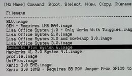
I put Alex’s software on an microSD card and have been testing LISA FPGA using that. Have any of you booted into Mac Works Plus System 6 using the H ROM and found the two included games freeze?

IMG_8972.jpeg

I can play Lode Runner but there is no sound, and every time I finish the first level, the LISA freezes.

Separately from that, every time I launch the Asteroids game, the Lisa freezes.

Just curious if the rest of you are finding that to be true when you boot your LISA FPGA from MacWorks Plus System 6.image".

I’ve never used a real Lisa before, so I have no idea if that happens on the machine or if this is pertaining to some bug.


BTW, the software compilation I am using on uSD card in my LISA FPGA was downloaded from Alex's Github here:


That contains these files:

1788143170426.png


But there is also a different link on his GitHub that leads you to a slightly different software compilation at the URL below (what I am NOT using):


That contains these files:

1788143364341.png
 
Last edited: