Hello everyone,
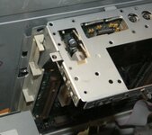
Last year I purchased half of a Performa 550 chassis that was missing the analog board and CRT. My goal was to use the included wiring harness to help me troubleshoot compatible 68k LC/Performa systems, the Color Classic, and Macintosh TV.
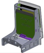
Sadly, I have a few of these boards that need help, and the way the logic board slides into the chassis, it doesn't allow you to probe the system while it's on, etc.
So today I took my first step into making this a reality. It's pretty janky, but as a concept it works!


Here's what I did and how it works:
1. I took an ATX power supply and used an ATX extension cable. This way I could splice wires without permanently modifying the power supply, if I needed to use the power supply for something else I could just unplug the extension cable.
From the ATX power supply I used two +5V cables (red), one +12V cable (yellow) and one black Ground cable. I spliced these to the two +5V, one +12V and two Ground (black and brown) cables from the Performa wiring harness. I bridged the black and brown ground cables together, but the system seems to work with the brown cable disconnected.
2. With just the power cables connected, the the ATX power supply is jumped to switch on when power is applied (by bridging the green "PS_ON" cable to ground). So when you connect a logic board... it springs to life! I plugged in a BlueSCSI and sure enough, I got a nice display of dancing lights when I applied power. This hack seems to skip any soft power circuitry. So you don't need to turn the system on via the keyboard.
3. Next, I wanted to try getting a video signal out to confirm the system is turning on properly.
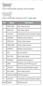
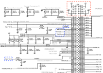
Using the LC 575 schematic floating around online, I was able to confirm the video signals I needed. Red, Green, Blue (plus their three ground signals), VSYNC and HSYNC. More may be needed for a proper picture... but I started with these as my friend @BigBadBiologist had some success when building his test bench set up. I used this pinout for a Mac 15-pin video connector as a guide and wired up those signals to the female end of a spare 15-pin connector I had.

I didn't want to rip apart the ribbon cable female edge connector that went to the analog board... So instead I clipped some plastic and used my SCSI edge PCB prototype to connect to the wires inside the connector. The spacing between the connectors was perfect, so I may design a PCB to help get access to these signals easier. This gave me access to every other pin (the odd pins, labeled A1 through A41 in the schematic), which was perfect. However I couldn't easily get access to the specific ground pins, so I just tied them to to each other temporarily.

4. I then plugged in a simple (non-dip) switch DB15 to VGA adapter, with a VGA cable going to my Atlona video scaler... to my surprise when I switched the power on, I got a video signal!
The Mac seems to work fine, and although the image is blurry, it's plenty good for testing to see if a board works.
What isn't working / Things to figure out:
1. In my testing I used a Color Classic logic board. I get no sound from the headphone jack on the logic board, or the headphone jack on the front of the little board (with the volume / picture controls and LED) on the Performa. This may be related to the infamous grounding issue.
2. The output resolution from the Mac (according to the video scaler) appears to be 640x350. I'm using a stock System 7.1 (Color Classic 401 System enabler). It could simply be that I'm not taping into a ground or additional video signal. Or it could a CC board not being happy in a "Performa" chassis. Because of this I only see the top left of the image of the screen, with the bottom and right being cut off.
3. The video image is very blurry, likely because in my testing I tied together the Red, Blue, and Green's ground video signals... and didn't really ground them. This is probably causing a LOT of analog noise. If I bothered to run the individual ground cables, this image would probably look better.
4. If the floppy drive is not connected, the system appears to think there's an unreadable floppy disk inserted! It'll show the floppy disk with an X on it on startup, and complain about an unreadable or locked disk. Connecting a floppy disk drive (even with no disk in it) seems to resolve this issue.
5. Use of a clock/PRAM battery is recommended, otherwise it takes a long time for the system to display an image.
Next steps...
1. Figure out how to get some sound out of the system.
2. Fix the video picture quality.
3. Test this set up with a Performa/LC 550/575 board to see if the video resolution issue is fixed.
4. If you have any ideas of how to make this better, I'm all ears. I'll try to get some close up photos and make a crude diagram soon.
Last year I purchased half of a Performa 550 chassis that was missing the analog board and CRT. My goal was to use the included wiring harness to help me troubleshoot compatible 68k LC/Performa systems, the Color Classic, and Macintosh TV.
Sadly, I have a few of these boards that need help, and the way the logic board slides into the chassis, it doesn't allow you to probe the system while it's on, etc.
So today I took my first step into making this a reality. It's pretty janky, but as a concept it works!
Here's what I did and how it works:
1. I took an ATX power supply and used an ATX extension cable. This way I could splice wires without permanently modifying the power supply, if I needed to use the power supply for something else I could just unplug the extension cable.
From the ATX power supply I used two +5V cables (red), one +12V cable (yellow) and one black Ground cable. I spliced these to the two +5V, one +12V and two Ground (black and brown) cables from the Performa wiring harness. I bridged the black and brown ground cables together, but the system seems to work with the brown cable disconnected.
2. With just the power cables connected, the the ATX power supply is jumped to switch on when power is applied (by bridging the green "PS_ON" cable to ground). So when you connect a logic board... it springs to life! I plugged in a BlueSCSI and sure enough, I got a nice display of dancing lights when I applied power. This hack seems to skip any soft power circuitry. So you don't need to turn the system on via the keyboard.
3. Next, I wanted to try getting a video signal out to confirm the system is turning on properly.
Using the LC 575 schematic floating around online, I was able to confirm the video signals I needed. Red, Green, Blue (plus their three ground signals), VSYNC and HSYNC. More may be needed for a proper picture... but I started with these as my friend @BigBadBiologist had some success when building his test bench set up. I used this pinout for a Mac 15-pin video connector as a guide and wired up those signals to the female end of a spare 15-pin connector I had.

I didn't want to rip apart the ribbon cable female edge connector that went to the analog board... So instead I clipped some plastic and used my SCSI edge PCB prototype to connect to the wires inside the connector. The spacing between the connectors was perfect, so I may design a PCB to help get access to these signals easier. This gave me access to every other pin (the odd pins, labeled A1 through A41 in the schematic), which was perfect. However I couldn't easily get access to the specific ground pins, so I just tied them to to each other temporarily.

4. I then plugged in a simple (non-dip) switch DB15 to VGA adapter, with a VGA cable going to my Atlona video scaler... to my surprise when I switched the power on, I got a video signal!
The Mac seems to work fine, and although the image is blurry, it's plenty good for testing to see if a board works.
What isn't working / Things to figure out:
1. In my testing I used a Color Classic logic board. I get no sound from the headphone jack on the logic board, or the headphone jack on the front of the little board (with the volume / picture controls and LED) on the Performa. This may be related to the infamous grounding issue.
2. The output resolution from the Mac (according to the video scaler) appears to be 640x350. I'm using a stock System 7.1 (Color Classic 401 System enabler). It could simply be that I'm not taping into a ground or additional video signal. Or it could a CC board not being happy in a "Performa" chassis. Because of this I only see the top left of the image of the screen, with the bottom and right being cut off.
3. The video image is very blurry, likely because in my testing I tied together the Red, Blue, and Green's ground video signals... and didn't really ground them. This is probably causing a LOT of analog noise. If I bothered to run the individual ground cables, this image would probably look better.
4. If the floppy drive is not connected, the system appears to think there's an unreadable floppy disk inserted! It'll show the floppy disk with an X on it on startup, and complain about an unreadable or locked disk. Connecting a floppy disk drive (even with no disk in it) seems to resolve this issue.
5. Use of a clock/PRAM battery is recommended, otherwise it takes a long time for the system to display an image.
Next steps...
1. Figure out how to get some sound out of the system.
2. Fix the video picture quality.
3. Test this set up with a Performa/LC 550/575 board to see if the video resolution issue is fixed.
4. If you have any ideas of how to make this better, I'm all ears.
Last edited:


