Color Classic analog board trouble

retr01

Senior Tinkerer
Jun 6, 2022
2,474
1
806
113
Utah, USA
retr01.com
Sure, but I'll have to design a new one for the Mystic.

The 2x AAA model won't be useful for it.

So, would the SE, SE/30, P475, IIci, etc, be different designs?

I am thinking...a 3D-printed battery case just that size and putting it in that battery socket, and the wires go to the rechargeable batteries placed elsewhere in Mac's case?

Should we start a new thread on this since PRAM impacts many Macs?
 
  • Like
Reactions: YMK

YMK

Active Tinkerer
Nov 8, 2021
394
325
63
So, would the SE, SE/30, P475, IIci, etc, be different designs?

Any Mac that takes a 1/2AA lithium could have a triple Eneloop holder stashed somewhere with a 5V input to charge the pack while running.

Wires would run from the Eneloop pack to a 1/2AA dummy 3D printed adapter inserted into the logic board battery holder.
 
  • Like
  • Love
Reactions: JDW and retr01

JDW

Administrator
Staff member
Founder
Sep 2, 2021
2,025
1,697
113
54
Japan
youtube.com
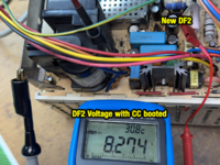
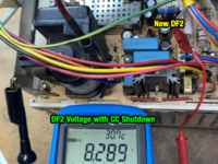
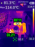
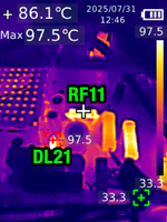
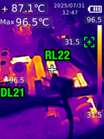
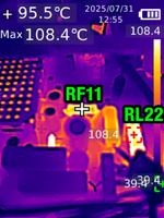
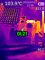
The 1N5344B works well for DF2, no picture adjustments needed.
I've used the full lead length and stood it up off the board.
Shown here, at 111.9°C
@YMK
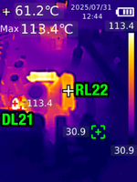
It's been more than 2 years since you swapped out the components shown below (replacing DL21 & DL22 with a single 1N5355B):

1752657948029.png


How is your machine doing today?

No unusual issues at all?


The reason I ask is because I never made time to solder in the components I bought because I was waiting to do a video about it. Then one important video popped up after another, and I'm only now sitting down writing a script.

My intention is to do this parts "upgrade" first, and then I plan to change my Standard 68.4v (60Hz) VGA Mod to the higher 84V (67Hz) Hi-Rez Mod, which will finally allow me to use any compatible motherboard, such as the stock CC board, LC520 board, and LC575 board (all of which I have). I just wanted to touch bases with you prior to filming.

Thanks!
 

JDW

Administrator
Staff member
Founder
Sep 2, 2021
2,025
1,697
113
54
Japan
youtube.com
Still working perfectly fine, though the machine spends most of its time turned (completely) off.
OK, but immediately after replacing those 5 components (only 5 because you used 1 diode instead of 2 for DL21/22), did your CRT content remain exactly the same as before, or did you need to make adjustments?
 

YMK

Active Tinkerer
Nov 8, 2021
394
325
63
OK, but immediately after replacing those 5 components (only 5 because you used 1 diode instead of 2 for DL21/22), did your CRT content remain exactly the same as before, or did you need to make adjustments?

I don't remember.
 

JDW

Administrator
Staff member
Founder
Sep 2, 2021
2,025
1,697
113
54
Japan
youtube.com
Because I am preparing a video on this topic, I have re-read this entire thread a couple times, and I'd like to address some loose ends...

I measured 47.5V at the center pin of the horizontal output transistor, but I'm not sure if this is the right place to get the B+ rail.
@YMK Very sorry to trouble you, but could you please mark on an analog board photo where that "horizontal output transistor" is located? I'm just curious where you were measuring when you started this thread.

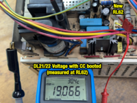
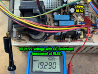
As you can see below, I have marked up a photo of the bottom of the Analog Board (taken prior to the VGA mod). At left, you can see that those super-hot DL21 & DL22 Zener Diodes connect to the equally super-hot RL62 47Ω resistor. The other side of those two diodes leads to the ground side of capacitors CL4 & CF9. Then in the upper right, you see that diode DP4 is where the Horizontal Deflection Voltage should perhaps be measured, on the component side of the board, of course. (My machine is disassembled and I've not measured there yet.)

CC-Analog-Board-BTM-Marked-Up.jpg
 

This Does Not Compute

Administrator
Staff member
Oct 27, 2021
333
479
63
www.youtube.com
Can I pile on with my own CC analog board problem? I recapped the AB in my Performa 275 recently, but afterwards the machine works fine with the exception that the CRT doesn't energize. It powers on, chimes, boots, etc but the screen stays black and there's no typical CRT noises except for the quick hum sound from the degauss coil when you flip the power switch on. The machine had no problems a couple of years ago when I got it, but foolishly I didn't test it again prior to recapping. (I used the same capacitor kit on 4 other CCs and those had no problems afterwards, so I know it's not my part selection.) Any suggestions for which parts of the AB I should focus on?
 

JDW

Administrator
Staff member
Founder
Sep 2, 2021
2,025
1,697
113
54
Japan
youtube.com
@This Does Not Compute
The only time I have ever had my screen stay black, hearing all the sounds you described AND booting too, is when I've got the CPU overclocked too fast for the VRAM SIMM. But I am using an LC575 board, and it seems you are using the stock CCII board, right? In other words, an LC550 board, I believe. I've never tried one of those boards, but I doubt you have it overclocked in any way, so there obviously must be some other reason for your black screen.

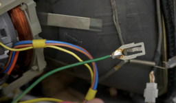
If you failed to reconnect something, it can have huge consequences. For example, @Kay K.M.Mods warned me in the past about ALWAYS reconnecting that green grounding wire to the main exposed metal ground during reassembly...

1753401929130.png

But I'm guessing you must have reconnected it prior to power on because Kay said it would destroy the motherboard if you didn't reconnect it, and since your machine boots, the MB must be OK.

Hmmm...

Are you 100% sure nothing else was left disconnected? If you are sure about that, have you checked solder joints for ALL the connectors?

I don't want to say it's impossible the flyback could have gone bad, but I've never read a single report about that in the Color Classic. Even so, the solder joints for that component and all the transformers are critical.

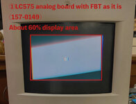
Also, in this thread we are talking about super hot components that can even sever traces on the solder side of the Analog Board. So you need to closely examine all the traces in the area of RL62 and the DL21/22 diodes, as shown here...

1753402159140.png


Lastly, are you 100% sure all the capacitors on soldered it with the right polarity direction? Really, it can be as simple as that, especially because it worked prior to recapping (even if that was a couple years ago).
 

Garrett

Tinkerer
Oct 31, 2021
118
123
43
South Carolina
I don't want to say it's impossible the flyback could have gone bad, but I've never read a single report about that in the Color Classic. Even so, the solder joints for that component and all the transformers are critical.
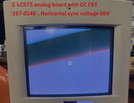
Unfortunately, I have two analog boards with bad flybacks. Every once in a while, they will "click" and the picture will shudder for a moment. I tried an LC575 flyback as a replacement. While it technically works, I was unable to get the geometry adjusted correctly.

Not super related to this thread, just wanted to provide my experience.
 
  • Like
Reactions: JDW