Color Classic analog board trouble

retr01

Senior Tinkerer
Jun 6, 2022
2,474
1
806
113
Utah, USA
retr01.com
Sure, but I'll have to design a new one for the Mystic.

The 2x AAA model won't be useful for it.

So, would the SE, SE/30, P475, IIci, etc, be different designs?

I am thinking...a 3D-printed battery case just that size and putting it in that battery socket, and the wires go to the rechargeable batteries placed elsewhere in Mac's case?

Should we start a new thread on this since PRAM impacts many Macs?
 
  • Like
Reactions: YMK

YMK

Active Tinkerer
Nov 8, 2021
397
327
63
So, would the SE, SE/30, P475, IIci, etc, be different designs?

Any Mac that takes a 1/2AA lithium could have a triple Eneloop holder stashed somewhere with a 5V input to charge the pack while running.

Wires would run from the Eneloop pack to a 1/2AA dummy 3D printed adapter inserted into the logic board battery holder.
 
  • Like
  • Love
Reactions: JDW and retr01

JDW

Administrator
Staff member
Founder
Sep 2, 2021
2,043
1,712
113
54
Japan
youtube.com
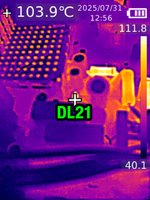
The 1N5344B works well for DF2, no picture adjustments needed.
I've used the full lead length and stood it up off the board.
Shown here, at 111.9°C
@YMK
It's been more than 2 years since you swapped out the components shown below (replacing DL21 & DL22 with a single 1N5355B):

1752657948029.png


How is your machine doing today?

No unusual issues at all?


The reason I ask is because I never made time to solder in the components I bought because I was waiting to do a video about it. Then one important video popped up after another, and I'm only now sitting down writing a script.

My intention is to do this parts "upgrade" first, and then I plan to change my Standard 68.4v (60Hz) VGA Mod to the higher 84V (67Hz) Hi-Rez Mod, which will finally allow me to use any compatible motherboard, such as the stock CC board, LC520 board, and LC575 board (all of which I have). I just wanted to touch bases with you prior to filming.

Thanks!
 

JDW

Administrator
Staff member
Founder
Sep 2, 2021
2,043
1,712
113
54
Japan
youtube.com
Still working perfectly fine, though the machine spends most of its time turned (completely) off.
OK, but immediately after replacing those 5 components (only 5 because you used 1 diode instead of 2 for DL21/22), did your CRT content remain exactly the same as before, or did you need to make adjustments?
 

YMK

Active Tinkerer
Nov 8, 2021
397
327
63
OK, but immediately after replacing those 5 components (only 5 because you used 1 diode instead of 2 for DL21/22), did your CRT content remain exactly the same as before, or did you need to make adjustments?

I don't remember.
 

JDW

Administrator
Staff member
Founder
Sep 2, 2021
2,043
1,712
113
54
Japan
youtube.com
Because I am preparing a video on this topic, I have re-read this entire thread a couple times, and I'd like to address some loose ends...

I measured 47.5V at the center pin of the horizontal output transistor, but I'm not sure if this is the right place to get the B+ rail.
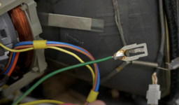
@YMK Very sorry to trouble you, but could you please mark on an analog board photo where that "horizontal output transistor" is located? I'm just curious where you were measuring when you started this thread.

As you can see below, I have marked up a photo of the bottom of the Analog Board (taken prior to the VGA mod). At left, you can see that those super-hot DL21 & DL22 Zener Diodes connect to the equally super-hot RL62 47Ω resistor. The other side of those two diodes leads to the ground side of capacitors CL4 & CF9. Then in the upper right, you see that diode DP4 is where the Horizontal Deflection Voltage should perhaps be measured, on the component side of the board, of course. (My machine is disassembled and I've not measured there yet.)

CC-Analog-Board-BTM-Marked-Up.jpg
 

This Does Not Compute

Administrator
Staff member
Oct 27, 2021
335
483
63
www.youtube.com
Can I pile on with my own CC analog board problem? I recapped the AB in my Performa 275 recently, but afterwards the machine works fine with the exception that the CRT doesn't energize. It powers on, chimes, boots, etc but the screen stays black and there's no typical CRT noises except for the quick hum sound from the degauss coil when you flip the power switch on. The machine had no problems a couple of years ago when I got it, but foolishly I didn't test it again prior to recapping. (I used the same capacitor kit on 4 other CCs and those had no problems afterwards, so I know it's not my part selection.) Any suggestions for which parts of the AB I should focus on?
 

JDW

Administrator
Staff member
Founder
Sep 2, 2021
2,043
1,712
113
54
Japan
youtube.com
@This Does Not Compute
The only time I have ever had my screen stay black, hearing all the sounds you described AND booting too, is when I've got the CPU overclocked too fast for the VRAM SIMM. But I am using an LC575 board, and it seems you are using the stock CCII board, right? In other words, an LC550 board, I believe. I've never tried one of those boards, but I doubt you have it overclocked in any way, so there obviously must be some other reason for your black screen.

If you failed to reconnect something, it can have huge consequences. For example, @Kay K.M.Mods warned me in the past about ALWAYS reconnecting that green grounding wire to the main exposed metal ground during reassembly...

1753401929130.png

But I'm guessing you must have reconnected it prior to power on because Kay said it would destroy the motherboard if you didn't reconnect it, and since your machine boots, the MB must be OK.

Hmmm...

Are you 100% sure nothing else was left disconnected? If you are sure about that, have you checked solder joints for ALL the connectors?

I don't want to say it's impossible the flyback could have gone bad, but I've never read a single report about that in the Color Classic. Even so, the solder joints for that component and all the transformers are critical.

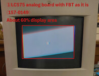
Also, in this thread we are talking about super hot components that can even sever traces on the solder side of the Analog Board. So you need to closely examine all the traces in the area of RL62 and the DL21/22 diodes, as shown here...

1753402159140.png


Lastly, are you 100% sure all the capacitors on soldered it with the right polarity direction? Really, it can be as simple as that, especially because it worked prior to recapping (even if that was a couple years ago).
 

JDW

Administrator
Staff member
Founder
Sep 2, 2021
2,043
1,712
113
54
Japan
youtube.com
The attachment in the opening post by @YMK has a text file extension even though it is HTML, making it hard to open. I converted it to Google Sheets and improved the styling and layout. Anyone can freely edit and update it here:

Color Classic ANALOG BOARD PARTS LIST
 

Garrett

Tinkerer
Oct 31, 2021
119
124
43
South Carolina
I don't want to say it's impossible the flyback could have gone bad, but I've never read a single report about that in the Color Classic. Even so, the solder joints for that component and all the transformers are critical.
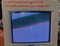
Unfortunately, I have two analog boards with bad flybacks. Every once in a while, they will "click" and the picture will shudder for a moment. I tried an LC575 flyback as a replacement. While it technically works, I was unable to get the geometry adjusted correctly.

Not super related to this thread, just wanted to provide my experience.
 
  • Like
Reactions: JDW

JDW

Administrator
Staff member
Founder
Sep 2, 2021
2,043
1,712
113
54
Japan
youtube.com
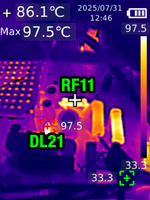
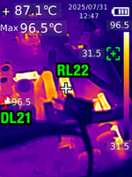
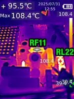
My filming of the component swap is finished. All replacement parts were raised up and off the PCB for better cooling. It passed the SMOKE TEST. No changes to the way the picture displays on the CRT either. Great so far!

This animated GIF shows the OLD and NEW components...

JDW_CC-AB-ComponentSwap.gif


The black stuff on the legs is regular heat shrink tubing, while the clear stuff is leftover silicone tubing I bought to swap the rollers on the inside of my Macintosh Portable's trackball. I used silicone tubing because those two resistors are big and heavy and I wanted to reduce strain on the solder pads. Also


VOLTAGE MEASUREMENTS

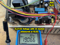
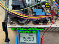
Sorry, but I completely forgot to make these measurements prior to the component swap. And while I am pleased to see the Zeners working to regulate voltage, I am curious if the stock Zener at DL21/DL22 regulated it closer to 18V. Because as you can see below, I am measuring just over 19v. Not a huge difference, but I'm just curious what the stock voltage is, if anyone coming along later reading this would like to measure your machine, with stock parts. RL62 is mounted at an angle, so I put a tiny dab of hot glue at the base of the two legs to keep it propped up.

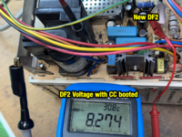
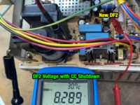
ZENER DF2

1753936150296.png 1753936177331.png


ZENER DL21/22

1753936310241.png 1753936288610.png


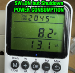
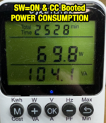
POWER CONSUMPTION

NOTE: I have an LC575 Mystic with CPU clock set to 50MHz. Setting CPU to the stock 33MHz drops power consumption to about 67W, down from 69.8W. Also note that I am in Japan and we use 100VAC, not 120VAC like the USA. YMK said earlier in this thread his consumption while Shutdown was 10W.

1753936449725.png 1753936466817.png


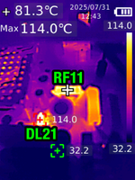
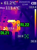
TEMPERATURE MEASUREMENTS

NOTES:
  • My Analog Board is Revision C (820-0360-C)
  • I have an LC575 Mystic motherboard with CPU clock set to 50MHz. 40mm Noctua 12v Fan on CPU. 36MB total RAM. ROM SIMM socket and SIMM installed. I also have a spinning platter HDD (not BlueSCSI). And I have the regular 68.4V VGA Mod installed on the A.B.
  • It's summertime. Ambient Room Temperature was 30°C.
  • With case back off, the internal fan cannot move air, so it's probably hotter than it otherwise would be with the back case on.

CC SW=ON but Shutdown for 15 min.

1753936754294.png


CC SW=ON but Shutdown for 16 min.

1753936822228.png


CC SW=ON and Booted for 2 min. (after having been in the Shutdown state for 16 min.)

1753937183481.png


CC SW=ON and Booted for 3 min.

1753937235007.png


CC SW=ON and Booted for 11 min.

1753937276505.png


CC SW=ON and Booted for 12 min.

1753936860850.png


REPLACEMENT PARTS

RL22

100Ω 5W 5% Axial Metal Oxide Resistor
Stock part: Body color=Cream, Dimensions=3.0mm x 8.75mm (possibly 1W Metal Film)

RL62
47Ω 5W 5% Axial Metal Oxide Resistor
Stock part: Body color=Blue, Dimensions=3.45mm x 8.5mm (possibly 1W Metal Oxide)

RF11
390Ω 5W 5% Axial Metal Oxide Resistor
Stock part: Body color=Blue, Dimensions=3.45mm x 8.5mm (possibly 1W Metal Oxide)

DF2
8.2V Zener 5W (Izt=150mA): 1N5344B-TP
Stock part: 8.2V 0.5W Izt=20mA 1N5237B

DL21 & DL22
Remove both stock parts. Replace with 1pc of 1N5355B 5W 18V (Izt=65mA) Zener
Stock parts: 18V 1.25W Izt=20.8mA 1N5931B


BUY THE PARTS

Mouser Cart: https://bit.ly/4oaw9nU
DigiKey Cart: https://www.digikey.com/short/d8m2zfdq
 
  • Like
Reactions: Nitram78

JDW

Administrator
Staff member
Founder
Sep 2, 2021
2,043
1,712
113
54
Japan
youtube.com
This evening after work, I was filming and testing for a solid 2 hours. During that 2 hours, I left the CC's Switch on back flipped ON. The machine was either booted or in the Shutdown condition during those 2 hours. Toward the very end, I left it in the Shutdown condition for a while because I know DL21 gets hotter than when the machine is booted. It hit 130°C...

1753960091301.png


It didn't stay at 130°C. It did fluctuate down to about 124°C, but didn't go below 124°C. The case back was off, but when ON there is no fan in the shutdown condition, so the ambient air around it with the case back on would be higher still.

The ambient temperature during all my testing was 30°C to 31°C, which is pretty warm, but still a good temperature to test. Suffice it to say, you should never leave a Color Classic with its back Power Switch turned ON when you leave it in a hot room during the summer months and you are away from home, even with the stock DL21/DL22 parts installed.

When I tested this back in 2023, my room was 22°C but later rose to 26°C. At that time, I measured about 105°C on the stock DL21/22 diode pair at 26°C ambient. HOWEVER, I had only been testing for about 25 minutes. Today's testing was 2 hours, and 4°C hotter too.

I think Apple used two zener diodes at DL21/DL22 even though that is bad practice simply because the surface area of two 1.3W Zeners is more overall than a single 5W Zener.

The datasheet for the 5W Zener that we are all using says this:

Max Operating Temperature for DC Conditions is 150°C, But not to Exceed 200°C
for Pulsed Conditions With Low Duty Cycle or Non−Repetitive.


Again, it hit 130°C while SHUTDOWN after 2 hours of testing but didn't really go past that, and after a while it dropped about 4-5°C down to about 125°C. That's under the 150°C limit, but still hotter than I would like.

@YMK and @This Does Not Compute , please let me know your thoughts.
 
  • Like
Reactions: YMK and Nitram78

YMK

Active Tinkerer
Nov 8, 2021
397
327
63
If you're worried about the temperature of the diode, you can fit a heatsink like this:


It's best to keep the diode orientation vertical if you can, for convection cooling. I haven't compared diameters so I can't comment on the fit.

I have made something similar for a diode on my passively cooled MacEffects SE out of copper tubing, since it no longer has the flyback cage to sink to.
 

JDW

Administrator
Staff member
Founder
Sep 2, 2021
2,043
1,712
113
54
Japan
youtube.com
Thank you for sharing your thoughts.

I have the replacement 18W Zener (1N5355B) soldered straight up on its legs (i.e., "vertical orientation"), and I have it raised up at least 1cm above the PCB. It is soldered into DL22 pads to keep the maximum distance from nearby capacitors. (Even then, the largest nearby cap reached 60°C and the smaller 66°C when I measured the replacement Zener to be 130°C.)

You linked a very nice looking heatsink on Amazon and I would love to use it, but alas, the inside diameter won't work because it says this:
ID (inside diameter): 0.23 inch / 6mm

The replacement 18V Zener we are all using is 1N5355B, which is a DO-15 body size, according to its datasheet...

1753998599677.png
1753998633303.png


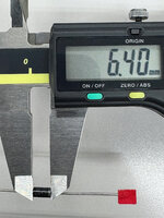
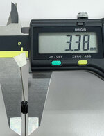
My spare 1N5355B measures as follows:

ZenerLength.jpg ZenerDiameter.jpg

Meaning, we cannot put a heatsink with 6mm inner diameter on a DO-15 diode that is between 2.60mm and 3.60mm in size.

My searches for DO-15 heatsinks has led no where.

So this is why I am curious if we should leave it as is or not. But bear in mind that the highest temperatures of that diode are reached when the machine is Shutdown and the back switch ON. Meaning, when NO FAN IS SPINNING. When you boot the machine, the temperature of that diode drops, and not because of any fan either (I had the case back off).

While we can just tell people to flip off the switch at back, what if they forget?

So long as the temperature doesn't exceed 140°C or so, it should be fine. Still too hot for my taste, but within specifications. Because 150°C is the line we must not cross (DC Operating).
 
Last edited:
  • Like
Reactions: YMK

This Does Not Compute

Administrator
Staff member
Oct 27, 2021
335
483
63
www.youtube.com
I'm personally not too worried about the temperatures, since I really only use my CC periodically and don't keep it plugged in all the time. I suspect a lot of folks -- but of course, not all -- have similar habits. And even then, if 140C is the highest we're really seeing, that's still sufficiently lower than 150C to leave enough buffer to account for ambient temperature. We could certainly try to dig up an alternative part that either has more surface area (for better heat dissipation and lower temperatures) or one rated for higher power but I'm not sure, as they say, that the juice is worth the squeeze.
 
  • Like
Reactions: JDW and YMK