Colour Classic Display Issues After 84v Mod + Recap

Doctorkillbydeath87

New Tinkerer
Sep 30, 2026
3
1
3
Hi Everyone, I recently attempted the 84v mod including the "beefy" upgrade as outlined by @JDW in his excellent youtube tutorials (thank you so much!). I also recapped a good portion of the analog board (the logic board was done by the previous owner). My CC was running flawlessly before my tinkering; it still boots fine, but I'm experiencing some major wonk on the display:
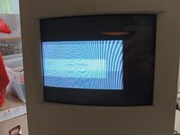
CCdisplaywoes.jpg

So far I have:
-Tested voltage @ J66 (84v)
-Replaced the new zener @ DL21/22 with the originals as I was worried installing heatsinks to the new one may have damaged it (no change).
-Tested for contact between new solder points and adjacent pads
-Reflowed a good portion of the board
-Checked for shorts caused by new soldering work

I am also looking for some advice on a small component that's detached on an LC 575 board. It is labeled L1 and need a replacement recommendation if possible:
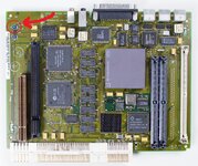
mysticboardcomponentl1.jpg

Hopefully I can get some direction from someone more knowledgeable than I, thanks in advance.
 

Attachments

  • CCdisplaywoes.jpg
    CCdisplaywoes.jpg
    1.9 MB · Views: 38

Mark_W

Tinkerer
Feb 2, 2026
50
37
18
The screen geometry and color are both way off which is a good hint that something's wrong with secondary voltage outputs from CRT transformer.Start with checking all voltages on CRT side, make sure 24V, 8.4V from transformer output are normal, as well as regulated 18V, 8.2V from zener diodes.

You can get the schematic here:

@jonschultz also has an excellent reverse engineering project on the XC1186B jungle chip and you can get more info here:

As for the LC575 board, L1 is a 100uH filter inductor for sound chip's 5V voltage supply. You can get replacements from any scrap board that uses DFAC-II chip, or just bridge it

1790825717793.png
 

jonschultz

New Tinkerer
May 16, 2026
30
21
8
USA
github.com
Excellent suggestions regarding the voltages to check. I was also going to mention that checking a flyback-generated voltage would be a good verification, as well. Most are pretty large, but one is reasonably low for safely measuring with a DMM. That's the one on pin 11 of the LM2418T (the cathode amplifier), which should be about 75V.
The screen geometry and color are both way off which is a good hint that something's wrong with secondary voltage outputs from CRT transformer.Start with checking all voltages on CRT side, make sure 24V, 8.4V from transformer output are normal, as well as regulated 18V, 8.2V from zener diodes.

You can get the schematic here:

@jonschultz also has an excellent reverse engineering project on the XC1186B jungle chip and you can get more info here:

As for the LC575 board, L1 is a 100uH filter inductor for sound chip's 5V voltage supply. You can get replacements from any scrap board that uses DFAC-II chip, or just bridge it

View attachment 30627
 

Doctorkillbydeath87

New Tinkerer
Sep 30, 2026
3
1
3
Thank you so much, I was able to spend a little bit of time tonight trying out these suggestions. I'm not overly familiar with reading electrical schematics so bear with me please. My results as best I can describe them:

On the LB:
DL21/DL22(zeners) = 18v
DF2 (zener) = 11v

On the CRT neck board:
Not sure what to label these as so, on the connector that attaches to the tube itself, moving clockwise starting from bottom left I tested each pad of the connector as follows:
0v, 40v, 39v, 0v, 89v, 88v, 88v, 0v, 260v, 0v

The four solder points at the bottom of the neck board with wires leading to the shielded cage on the LB, left to right:
88v, 89v, 89v, 0v

I will add some pictures with labels tomorrow to aid I'm my description.

I also measured the leads coming off the LB leading directly to the CRT but realized after I must have wrote the wrong IDs down for them after referencing a high res picture of the board. I will remeasure and post tomorrow, but here is what I noted:
HL 2: 183v
HL 3: 0v
HL 4/HL 5: 40v

If any of this is useful off hand to anyone in coming up with a diagnoses please let me know, and thanks again! I will keep trying in the meantime.
 

jonschultz

New Tinkerer
May 16, 2026
30
21
8
USA
github.com
DL21/22 voltage is ok, but DF2 voltage is much higher than it should be (8.2V). Did you install the correct zener diode? Also double check those power resistors and caps nearby, make sure you didn't install anything wrong.
Yeah I agree, the DF2 voltage is suspiciously high. Do you have the correct value for RF11, which biases DF2? I think it should be 370 Ohms.
 
  • Like
Reactions: Doctorkillbydeath87

Doctorkillbydeath87

New Tinkerer
Sep 30, 2026
3
1
3
DL21/22 voltage is ok, but DF2 voltage is much higher than it should be (8.2V). Did you install the correct zener diode? Also double check those power resistors and caps nearby, make sure you didn't install anything wrong.
Wow, I indeed did not! When I was making up my digikey cart I must have accidently replaced the 8.2v zener with an additional 18v!
I put in the original 8.2v zener and was met with a much better picture upon boot. Can't believe it was something so simple but I'm glad.

IMG_20261002_100710_303.jpg

Pardon the picture quality, the colour in reality is the expected grey, black and white. And very stable. Just need to figure out the positioning issue now.

575 board is also booting just fine with L1 bridged. Thanks so much for the advice, you guys really are Lifesavers.
 
Last edited:
  • Like
Reactions: bakkus