Colour Classic Display Issues After 84v Mod + Recap

Doctorkillbydeath87

New Tinkerer
Sep 30, 2026
7
1
3
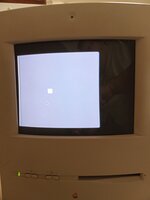
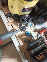
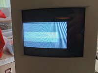
Hi Everyone, I recently attempted the 84v mod including the "beefy" upgrade as outlined by @JDW in his excellent youtube tutorials (thank you so much!). I also recapped a good portion of the analog board (the logic board was done by the previous owner). My CC was running flawlessly before my tinkering; it still boots fine, but I'm experiencing some major wonk on the display:
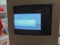
CCdisplaywoes.jpg

So far I have:
-Tested voltage @ J66 (84v)
-Replaced the new zener @ DL21/22 with the originals as I was worried installing heatsinks to the new one may have damaged it (no change).
-Tested for contact between new solder points and adjacent pads
-Reflowed a good portion of the board
-Checked for shorts caused by new soldering work

I am also looking for some advice on a small component that's detached on an LC 575 board. It is labeled L1 and need a replacement recommendation if possible:
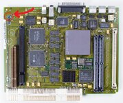
mysticboardcomponentl1.jpg

Hopefully I can get some direction from someone more knowledgeable than I, thanks in advance.
 

Attachments

  • CCdisplaywoes.jpg
    CCdisplaywoes.jpg
    1.9 MB · Views: 57

Mark_W

Tinkerer
Feb 2, 2026
52
39
18
The screen geometry and color are both way off which is a good hint that something's wrong with secondary voltage outputs from CRT transformer.Start with checking all voltages on CRT side, make sure 24V, 8.4V from transformer output are normal, as well as regulated 18V, 8.2V from zener diodes.

You can get the schematic here:

@jonschultz also has an excellent reverse engineering project on the XC1186B jungle chip and you can get more info here:

As for the LC575 board, L1 is a 100uH filter inductor for sound chip's 5V voltage supply. You can get replacements from any scrap board that uses DFAC-II chip, or just bridge it

1790825717793.png
 

jonschultz

New Tinkerer
May 16, 2026
37
23
8
USA
github.com
Excellent suggestions regarding the voltages to check. I was also going to mention that checking a flyback-generated voltage would be a good verification, as well. Most are pretty large, but one is reasonably low for safely measuring with a DMM. That's the one on pin 11 of the LM2418T (the cathode amplifier), which should be about 75V.
The screen geometry and color are both way off which is a good hint that something's wrong with secondary voltage outputs from CRT transformer.Start with checking all voltages on CRT side, make sure 24V, 8.4V from transformer output are normal, as well as regulated 18V, 8.2V from zener diodes.

You can get the schematic here:

@jonschultz also has an excellent reverse engineering project on the XC1186B jungle chip and you can get more info here:

As for the LC575 board, L1 is a 100uH filter inductor for sound chip's 5V voltage supply. You can get replacements from any scrap board that uses DFAC-II chip, or just bridge it

View attachment 30627
 

Doctorkillbydeath87

New Tinkerer
Sep 30, 2026
7
1
3
Thank you so much, I was able to spend a little bit of time tonight trying out these suggestions. I'm not overly familiar with reading electrical schematics so bear with me please. My results as best I can describe them:

On the LB:
DL21/DL22(zeners) = 18v
DF2 (zener) = 11v

On the CRT neck board:
Not sure what to label these as so, on the connector that attaches to the tube itself, moving clockwise starting from bottom left I tested each pad of the connector as follows:
0v, 40v, 39v, 0v, 89v, 88v, 88v, 0v, 260v, 0v

The four solder points at the bottom of the neck board with wires leading to the shielded cage on the LB, left to right:
88v, 89v, 89v, 0v

I will add some pictures with labels tomorrow to aid I'm my description.

I also measured the leads coming off the LB leading directly to the CRT but realized after I must have wrote the wrong IDs down for them after referencing a high res picture of the board. I will remeasure and post tomorrow, but here is what I noted:
HL 2: 183v
HL 3: 0v
HL 4/HL 5: 40v

If any of this is useful off hand to anyone in coming up with a diagnoses please let me know, and thanks again! I will keep trying in the meantime.
 

jonschultz

New Tinkerer
May 16, 2026
37
23
8
USA
github.com
DL21/22 voltage is ok, but DF2 voltage is much higher than it should be (8.2V). Did you install the correct zener diode? Also double check those power resistors and caps nearby, make sure you didn't install anything wrong.
Yeah I agree, the DF2 voltage is suspiciously high. Do you have the correct value for RF11, which biases DF2? I think it should be 370 Ohms.
 
  • Like
Reactions: Doctorkillbydeath87

Doctorkillbydeath87

New Tinkerer
Sep 30, 2026
7
1
3
DL21/22 voltage is ok, but DF2 voltage is much higher than it should be (8.2V). Did you install the correct zener diode? Also double check those power resistors and caps nearby, make sure you didn't install anything wrong.
Wow, I indeed did not! When I was making up my digikey cart I must have accidently replaced the 8.2v zener with an additional 18v!
I put in the original 8.2v zener and was met with a much better picture upon boot. Can't believe it was something so simple but I'm glad.

IMG_20261002_100710_303.jpg

Pardon the picture quality, the colour in reality is the expected grey, black and white. And very stable. Just need to figure out the positioning issue now.

575 board is also booting just fine with L1 bridged. Thanks so much for the advice, you guys really are Lifesavers.
 
Last edited:
  • Like
Reactions: bakkus

Doctorkillbydeath87

New Tinkerer
Sep 30, 2026
7
1
3
Well, I seem to have a new issue with the machine...

I finished recapping the entire analog board, installing the correct diode, adjusting the display, and got as far as installing a copy of os 7.5.3 to a bluscusi. There where a few hiccups along the way:

-a couple random instant shutdowns
-screen had an intermittently appearing blue tint (seemed to have stabilized after running the machine for a while)

As I said I was able to run long enough to install the OS but upon attempting to boot afterwards, the machine simply "flashes" when holding down the power button (keyboard blinks and analog board makes some sound).

Same results testing with my 575 logic board.

This is with my original CC board plugged in. With my LC 575 board plugged in I get no response from pressing the power key whatsoever.

Troubleshooting so far:
-Verified caps and components are all correct (some are over voltage and raised due to size but exposed legs are insulated- potential issue?)
-Keyboard and cable have been checked on another machine
-inspected for shorts/solder bridges/bad contact.
-inspected and cleaned analog/logic edge connectors.

Would appreciate any suggestions as to where to start tracing for problems, thanks!
 

Attachments

  • VID_20261014_124307.mp4
    3.7 MB · Views: 0

jonschultz

New Tinkerer
May 16, 2026
37
23
8
USA
github.com
When a CC seems to be this dead, I recommend checking some of the low-voltage supplies. Many of them will normally be running even without booting (shouldn't even require an installed logic board), you simply have to have the hard power switch on. You can check the 8.3V and 24V supplies first, which you can probe at RV26 and RF19 respectively (either side of the component will read close to the nominal value, measured relative to ground). There are sort of in the middle area of the AB.
 

Doctorkillbydeath87

New Tinkerer
Sep 30, 2026
7
1
3
Thanks! I metered those two points and it looks like my voltage is decent, I also measured each end of the resistor:

RV26: 7.95v/8.1v
RF19: 23.61v/23.71v

Edit:
After testing voltages around the board, IP7 (TDA 4605-2 chip) gave off a small spark when tested, and now the CC doesn't respond to the power key at all. Tried replacing with a TDA 4605 off a Classic II AB but no change in behaviour.
 
Last edited:

jonschultz

New Tinkerer
May 16, 2026
37
23
8
USA
github.com
That's a good sign because it means the AC section and the CRT supply section are working. The logic board supply side could still have a problem. Which TDA4605 did you have discharge on? There are two, one for each of the switching supply transformers. In any case, I think the CRT side (which definitely runs continuously if the hard power switch is on) also supplies 5V standby power. You can check this at pin 1 of BD11, a 2-pin header in the front-left corner, but I suspect this will be OK. Similarly, you should see the 5V on the lower-left pin of the logic board ADB connector (you'll have to stick a piece of wire into it to probe). If that's not reading right, it could point to a problem with the board connector, but one step at a time.
 

Doctorkillbydeath87

New Tinkerer
Sep 30, 2026
7
1
3
That's some good news at least!

BD11 is receiving 5v on the right pin (looking at the AB from the rear).

Also receiving 5v from both ADB ports on the original CC LB (5v on the keyboard end of the cable as well)

Tested the soft power button on 3 different known working keyboards, no response from the machine.

TDA 4605 that sparked was at IP7, on the left of the board near the yellow transformer. Again I replaced a 4605-B with a 4605 from a Classic II AB, can swap it out if it's not in fact compatible.

Also noticed my fan is no longer functioning, tested with the LB installed and removed. I metered the pins but can't read any voltage.
 

Attachments

  • 17920666825338311714744414592068.jpg
    17920666825338311714744414592068.jpg
    1.6 MB · Views: 4
Last edited:

jonschultz

New Tinkerer
May 16, 2026
37
23
8
USA
github.com
Definitely seems like something is wrong with the supply section for the logic board power, right near IP7, though it's not necessarily the bad part. Everything sort of "north" of IP7 toward the front of the machine is related to logic board power, and it won't normally be running unless soft-power is initiated. You can start by testing individual components, to the extent that you can, and looking for bad solder joints. Did you recently replace any of the components in this area?
 

Mark_W

Tinkerer
Feb 2, 2026
52
39
18
Power supply for CRT part and logic board are mostly independent, and from your readings the CRT part should be working fine.

5V standby voltage is generated by CRT part and it's present so we can rule it out.

You can jump start the logic board power supply by shorting BD11 with a jumper. If soft power part is working, QP11 should turn off and CP34 will charge up from mains power through RP23 till it reaches TDA4605's power on threshold, after which the switching mosfet should start working and CP34 will be charged by auxiliary winding from the transformer and you should have voltage outputs from secondary. If you don't see voltage on TDA4605's pin 6 then something's wrong with soft power control, check the surrounding circuit near optocoupler IP10:
1792091718654.png


If you see voltage on pin 6 of IP7 then the issue is with the switching power supply itself. First of all replace TDA4605, optocoupler CNY17-3 and switching mosfet IRFBC40. From my experience they should be replaced at the same time, one blown mosfet usually takes out the other 2 components, also the optocoupler's gain drops over time as ir led gets dimmer.

With all mentioned components replaced it should rule out any issue on the primary side, if you still don't get voltage output then something's wrong with voltage feedback control circuit around IP9:

1792092567770.png


I had a very stubborn analog board before, replaced everything I suspected and it still won't work, logic board power supply keeps entering protection mode. Eventually I just nuked everything on the logic board power supply section and added an extra 5V/12V/-12V power supply in place, plus a relay controlled by soft power signal. If you have to go down this route you can check my previous post for details
 
  • Like
Reactions: jonschultz