Design68: A 65% replacement keyboard using AppleDesign controllers

demik

Tinkerer
Oct 11, 2021
42
36
18
Was working on this since a few weeks. Since it works, I'm gonna post that here.

One common issue I and a few other folks have is that while Apple Extended Keyboards are great (and still my favorite keyboard), they are kinda big for test benches or if your retro corner is small. That and we have too much dead AppleDesigns siting around

The following idea was reusing the keyboard controller from a dead AppleDesign into a custom new keyboard.

Please note that this is ISO only for now, but everything including PCBs will be put on GitHub for people to mess with !
I only tested with an ALPS ISO 341-0001 Controller. Others controllers will probably need a different PCB

What's needed​

- Tester68 keyboard from CIY
- A dead AppleDesign keyboard
- 70 MX styled switches (5 pins recommended)
- 65% Apple styled keycap set
- custom PCB
- 2U keycap stabilizer
- some tools (a Dremel would help greatly)

Build log​

• Solder everything on the back of the PCB. The controller needs to be socketed

Design68_PCB_front.jpeg


• Cut every leg as close as possible to the PCB

Design68_PCB_back.jpeg


• Convert plate from ANSI to ISO

Design68_converted_plate.jpeg


• Remove batteries holder, USB receiver. Cut case for ADB cables and ADB socket

Design68_cable_cuts.jpeg


• Reassemble PCB / gasket / plate / switches (need to temporary remove the controller here)

Design68_mounted_plate.jpeg


• Route cables. You may want to use some glue on the panel here. This is to avoid yanking the cable out of the PCB

Design68_routed_cable.jpeg


• Keycap time and it's done ! Please check if the ADB socket hole can accept actual connector, you may need to enlarge it somewhat

Design68_back.jpeg


Builds​

To give you some ideas, two keyboards are already build:

Build #1
- Case: Tester68 translucent black case
- PCB: Black, red LEDs
- Switches: AEBoard Naevies v2 (Alphas), Cherry MX Clear (Mods)
- Keycaps: Keychron ISO-FR ABS

Build #2
- Case: Tester86 translucent purple case
- PCB: Black, blue LEDs
- Switches: Cherry MX Black
- Keycaps: Keychron ISO-UK PBT Retro

Design68_UK%2BFR.jpeg


Mandatory family pics (AEKII uncle for scale)

Design68_AEKII.jpeg


Everything is OpenSource and published on GitHub here
Gerbers files can be downloaded from here

On a side note, We know that there is at least 2 or 3 ISO AppleDesign variants, which may have different controllers (same with ANSI)
I'm trying to document which AppleDesigns are suitable for this project. Can some of you please check what's inside their keyboards ?

Thanks for the help
 

RetroTheory

Tinkerer
Oct 17, 2021
77
118
33
Great project , I have a few different ones

Made in Czech Rep. 3 Screws on base
cr.jpg
c2r.jpg


Assembled in Thailand, 4 screws on base
th.jpg

th2.jpg
 

RetroTheory

Tinkerer
Oct 17, 2021
77
118
33
There is also this clone made by ALPS (MEADB-), But inside we have a familiar IC. Not sure if the membrane layout is the same though


20230912_125559.jpg
20230912_125419.jpg
20230912_125520.jpg
 

demik

Tinkerer
Oct 11, 2021
42
36
18
Thanks @RetroTheory and @François

I didn't know about the ALPS clone.

About the NMB one, it looks like that's really a different controller. The KS88C0504 has internal pull-up controllers, while ion the NMB PCB, it's external. Also a few more things that aren't there on the ALPS version.

For reference, here is the one I used:

820-0020_front.jpg


820-0020_back.jpg
 

demik

Tinkerer
Oct 11, 2021
42
36
18
Thanks to everyone photos who helped: ANSI version of the PCB !

It turns our the controller is dual mode, and will boot into ISO or ANSI mode when installed in the respective PCB.
You can find the ANSI Gerbers files here
 
  • Like
Reactions: RetroTheory

François

Tinkerer
Aug 9, 2022
90
39
18
France
It’s a really cool project, but I was wondering wether I needed to make it. Turns out I already have a compact ADB keyboard, that even include a trackpad: the one that comes with the TAM!
 
  • Like
Reactions: Patrick and wottle

wottle

Active Tinkerer
Oct 30, 2021
526
274
63
47
Fort Mill, SC
It’s a really cool project, but I was wondering wether I needed to make it. Turns out I already have a compact ADB keyboard, that even include a trackpad: the one that comes with the TAM!
I do as well, however:
1. I don't want to put the wear and tear on that keyboard
2. That arrow key layout!

I'm going to be trying to put one of these together. Only have one keyboard with the correct ANSI chip, but will be a fun project. Steal some switches from my son and will be nice to have a new ADB keyboard with modern mechanical switches.
 

wottle

Active Tinkerer
Oct 30, 2021
526
274
63
47
Fort Mill, SC
@demik , I got my PCBs in today. I am trying to re-use the ADB cable from my original keyboard. I'm not too familiar with the pin markings for the cable (G V A P E). The wires in my cable are black, white, red, green, and blue. Any help on which goes to which? Or if you know which pin on the ADB connector each goes to, I can tone them out.

Also, the socket for the controller covers up some of the switch pin locations. I assume you solder those key switches in first, cut the pins close, and then put the socket on?

Appreciate the work you put in to it! Excited to have a modern ADB keyboard I can play around with!
 
Last edited:
  • Like
Reactions: demik

wottle

Active Tinkerer
Oct 30, 2021
526
274
63
47
Fort Mill, SC
OK, So I answered my own questions. First, I made a massive mistake soldering on the key switches without realizing they need to go on AFTER the red rubber later and the top plate (the part with the stabilizers). So desoldering all those switches was fun!

The correct order of assembly, for those who haven't built their own keyboard is as follows:

  1. Solder all the components on the bottom of the board, EXCEPT for the 40 pin socket for the controller chip. See notes below about soldering the ADB cable.
  2. Cut the pins on the top side of the board as close as possible, particularly any that will be sticking out where a key switch will be installed.
  3. Before soldering down the socket, I'd recommend test fitting it, marking where the pins for the key switches will be that will be under the socket. Unfortunately, there are some pins that will be hard to reach if you don't clear away some of the plastic from the bottom of the socket. I used my soldering iron to melt away material where the pins would be. There were 4 pins covered by the socket plastic, at least on the sockets I used. After making room and verifying the location was correct with a test fitting, solder down the socket.
  4. Once all the components on the bottom of the board have been installed, you can add the rubber gasket and top plate to the top of the board (no screws to hold it in place, so just position it for now.
  5. At this point, I added about a half dozen key switches. I used 5 pin types that were meant for hot swapping and they clipped into place nicely. I positioned them in the middle (where the socket is as those will be tricky to solder in with the socket in the way, and then the corners. Note that my PCBs from JLCPCB were a bit warped, so the board was pulling away and I needed to apply pressure to get the board snug to the top plate. Once the switches were soldered in, they will hold the PCB tight against the top plate and it was pretty flat.
  6. It this stage, I went ahead and tested it out the keyboard and the few switches I had soldered by plugging it into a Mac that doesn't require soft power, plugging a mouse into it. Fired up Mac OS 7, ensured the mouse was working through the keyboard's ADB port. Then went into Key Caps control panel and ensured the key presses were registering.
  7. Next, I soldered the rest of the switches, except for those with LEDs under them.
  8. Solder on the LEDs and the final key caps.
  9. Next, I did a test fitting in the case, and marked with a sharpie where I would remove material. For inside the batter case, I removed the area as shown by OP around where the USB wireless adapter was being held. This is where the ADB cable will come out of the case. Make sure you cut this big enough to pull the ADB connector through. I also cut out a section in the batter compartment for the ferrule to have room. It seems too tight to have the cable fold back on itself like the OP did if the ferule is on the cable. I also had to grind a little notch in the battery cover to allow the cable to exit the battery compartment when closed. For the ADB port, I marked the center location and then used a drill bit to cut a perfect hole where the ADB port will be. Looks nicer than what it would look like if I had hacked at it with my Dremel.
  10. Assmbly time! Pull the soldered on ADB cable through the hole in the battery compartment, all the way until the PCB is seated in the case with all the screw locations lined up. Test the hole you made for the ADB port to ensure you can plug an ADB cable into it. If it looks good, you can grab some of the screws you have from the disassembly of the Tester68 keyboard and screw the PCB, gasket, and top plate down into the case.
  11. (Optional), I like the black cable look, so I used Duplicolor Matte Black Vinyl and Carpet Dye to paint the ADB cable black. Matches the black accessories that came with the Mac TV perfectly.
  12. Route the cables as shown by OP, reinstall the battery cover. Improvise strain relief and secure the cable as you see fit.
  13. Install key caps!

Hopefully having the steps laid out will prevent others from making the time intensive mistakes I made.


OK, as for the ADB cable connectors, I mapped out the connection, just in case the internal wire colors are different on different ADB cables. I used two ADB cables. One that came with my AEK, and another standalone ADB cable that has a coiled section, which I like for keyboards. For the AEK cable, the internal wires were black, green, red, white, and blue. For the standalone cable, the internal wires were orange, red, black, and tan, with the shell connected to the uncoated wires going around the shielding.

So, Looking at an ADB cable head on, it looks like this:

Code:
     ______
  2 / *  * \ 3
 1 | *    * | 4
    \  ◼︎   /
     ------

I've number the pins. starting with the left lower pin being 1, going clockwise to the right lower pin being 4.

So, the connectors on the PCB are labeled G V A P E. Below is a table of the pin, and the corresponding wire to connect to it for the two cables I used. I'd double check your cable in case the wire colors are different.

PCB labelADB pin numberAEK Cable wire colorStandalone coiled cable wire color
G3greenorange
V2redred
A1blueblack
P4whitetan
Eshellblackbare wire in sheathing

I tested both wires out on two different boards I was assembling and the wiring checks out as far as I can tell.
 
Last edited:
  • Like
Reactions: demik and François

demik

Tinkerer
Oct 11, 2021
42
36
18
Hello,

Nice detective job !

I'm not 100% if Apple cables are all the same, but you got that right. The letters stand for :
- G = ground (green)
- V = VCC / +5V (red)
- A = ADB bus (blue)
- P = Power Trickle (white)
- E = Earth / Shield (thick black)

Also thanks for your build log, it will help people more than mine did. I did the socket before the key switches, by pressing them little more the pin will go under the socket. That's socket and switch dependant I guess

If that helps, the other LEDs are :
- NUM Led is under FN (which is the power button)
- Scroll is under Home

You can make them blink with apps like https://macintoshgarden.org/apps/adb-express.
I had another one which would blink the LEDs on Network or LED activity, unfortunately I cannot find it anymore...

The accent key LED is always on and totally optional

Any pictures of your build ? Did you use the ANSI or ISO PCB ?
 

Trash80toG4

Active Tinkerer
Apr 1, 2022
910
260
63
Bermuda Triangle, NC USA
VERY cool! Was thinking along these lines a LONG time ago, but back-burnered because I wondered how the flex switches differed electrically from mechanical switches? Might there be a problem with such, if so?
 
  • Like
Reactions: wottle

wottle

Active Tinkerer
Oct 30, 2021
526
274
63
47
Fort Mill, SC
Hello,

Nice detective job !

I'm not 100% if Apple cables are all the same, but you got that right. The letters stand for :
- G = ground (green)
- V = VCC / +5V (red)
- A = ADB bus (blue)
- P = Power Trickle (white)
- E = Earth / Shield (thick black)

Also thanks for your build log, it will help people more than mine did. I did the socket before the key switches, by pressing them little more the pin will go under the socket. That's socket and switch dependant I guess

If that helps, the other LEDs are :
- NUM Led is under FN (which is the power button)
- Scroll is under Home

You can make them blink with apps like https://macintoshgarden.org/apps/adb-express.
I had another one which would blink the LEDs on Network or LED activity, unfortunately I cannot find it anymore...

The accent key LED is always on and totally optional

Any pictures of your build ? Did you use the ANSI or ISO PCB ?
Thanks for the response and for building out this PCB!

I used the ANSI layout. I was waiting on key caps to come in before posting pictures, but ended up harvesting the caps from a Kechron K2 I had. It looks good. I'm not sure if I used the wrong LEDs, but I don't get any of the LEDs to work. I'm thinking I may have fried the LEDs with too much heat for too long. I'll see if I can be more careful on my second keyboard when my tester68 comes in.

IMG_0168.jpeg

I need to find another key cap for the power button (probably just throw the fn key back on there), because the red key is meant for the top row, which has a different height / pitch.
IMG_0169.jpeg


A couple of ideas for improvements:

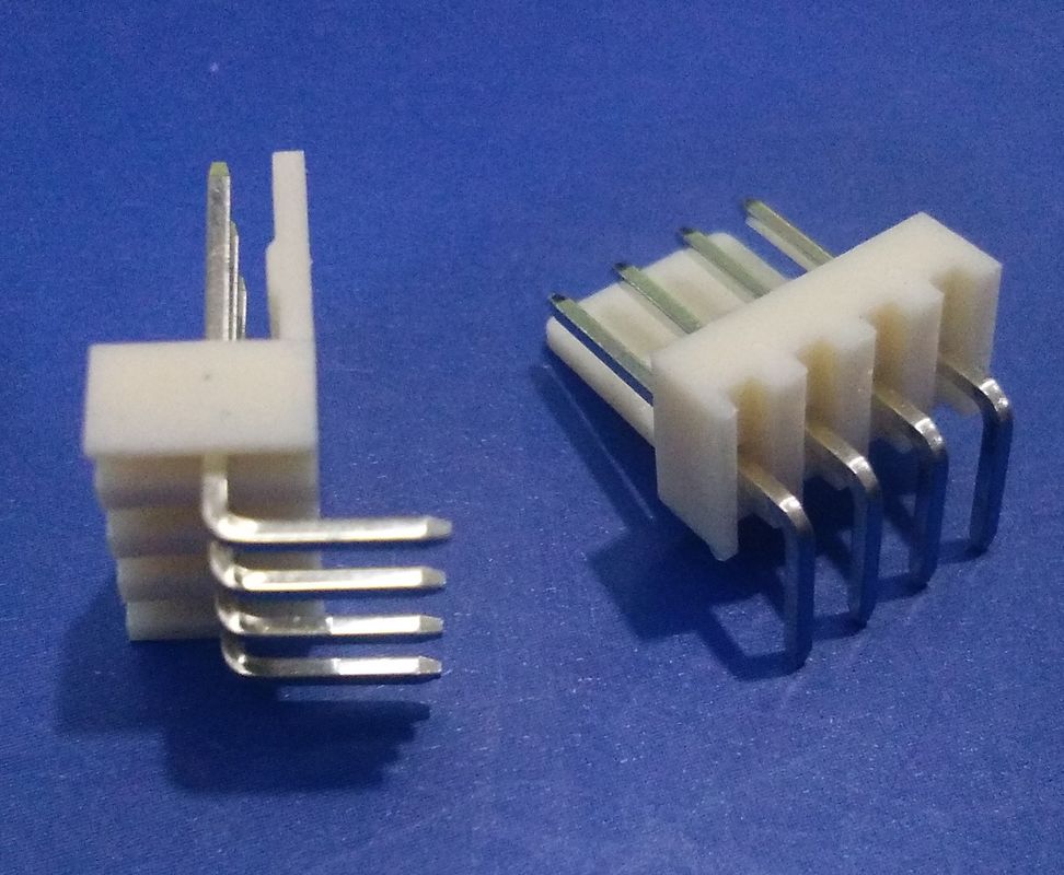
At least for me, soldering the ADB wire directly to the board made for a challenge. The wires, especially the ones on the standalone, coiled ADB keyboard, seems to be a pretty weak connection. Would it possible to adjust the spacing and allow for a connector to be soldered on to the wires and then connected with a JST connector of some time. Maybe something like this:
pl21964911-jvt_wire_to_board_connector_pitch_2_54mm_4pin_dip_style.jpg

Or, possibly like some of Apple's ADB cables, make two ADB ports on the back. So replace the cable connector for another mini DIN4 connector? One goes to the computer, another to the mouse?

Second, and this is probably way too much work, but it would be really cool if you could make one with hot swappable key switches. Maybe even be able to harvest the hot swap pin connectors from the Tester68?

Third, I had a bit of a hard time soldering the switches under the 40 pin socket. If they switches were hot swappable, there wouldn't be the need. If not, shifting the 40 pin socket location just a few mm up would probably make this part much easier.

Just some thoughts I had while working on it that might be worth considering if you make other changes to the board.

Additionally, it would be great if there were a new stock source for the controller chips, but I know that is probably a tall ask. I'll just have to be on the lookout for more AEKs that are in bad shape and I can pul the controller from.
 

demik

Tinkerer
Oct 11, 2021
42
36
18
VERY cool! Was thinking along these lines a LONG time ago, but back-burnered because I wondered how the flex switches differed electrically from mechanical switches? Might there be a problem with such, if so?

Might be. The loop resistance of a membrane "switch" is about 100-200Ω and act as a current limiting resistor. When switching to standard switches, it goes down to 0Ω, so you have to be careful in some cases to not short the controller.

The 341-0001 has 33kΩ internal pull-up resistors, so 33kΩ or a 33.1kΩ resistance to ground is a rounding error
 

demik

Tinkerer
Oct 11, 2021
42
36
18
Thanks for the response and for building out this PCB!

I used the ANSI layout. I was waiting on key caps to come in before posting pictures, but ended up harvesting the caps from a Kechron K2 I had. It looks good. I'm not sure if I used the wrong LEDs, but I don't get any of the LEDs to work. I'm thinking I may have fried the LEDs with too much heat for too long. I'll see if I can be more careful on my second keyboard when my tester68 comes in.
Thats weird, maybe the LEDs are backwards ?
I need to find another key cap for the power button (probably just throw the fn key back on there), because the red key is meant for the top row, which has a different height / pitch.
View attachment 13744

This does look so good with the Kingston Trackball !

A couple of ideas for improvements:

At least for me, soldering the ADB wire directly to the board made for a challenge. The wires, especially the ones on the standalone, coiled ADB keyboard, seems to be a pretty weak connection. Would it possible to adjust the spacing and allow for a connector to be soldered on to the wires and then connected with a JST connector of some time. Maybe something like this:
pl21964911-jvt_wire_to_board_connector_pitch_2_54mm_4pin_dip_style.jpg

The PCB was designed to use an angled right 2.54mm header or a connector like this (see the silkscreen). I soldered the cables because I've got no patience. The internal connector is a good idea as the wires are indeed pretty weak.

Or, possibly like some of Apple's ADB cables, make two ADB ports on the back. So replace the cable connector for another mini DIN4 connector? One goes to the computer, another to the mouse?

Toyed with that idea for a bit. Had clearance issues with either switches or the case.
There is another way to do it tho:

The mini DIN port can be used as an input port as well. How do you connect the mouse then ? Just build an Y ADB cable with a female socket for the mouse like some ADB devices did back then (either at the keyboard or Mac end)

Second, and this is probably way too much work, but it would be really cool if you could make one with hot swappable key switches. Maybe even be able to harvest the hot swap pin connectors from the Tester68?

That should be easy if I can convert he current footprint easily. it will however needs SMD LEDs or no LEDs at all as hot swap switchs cannot support THT LEDs

As for harvesting hot swap pins I kinda melted like 20% of them while trying that but patience etc.

Third, I had a bit of a hard time soldering the switches under the 40 pin socket. If they switches were hot swappable, there wouldn't be the need. If not, shifting the 40 pin socket location just a few mm up would probably make this part much easier.

Just some thoughts I had while working on it that might be worth considering if you make other changes to the board.

Additionally, it would be great if there were a new stock source for the controller chips, but I know that is probably a tall ask. I'll just have to be on the lookout for more AEKs that are in bad shape and I can pul the controller from.

Noted thanks. Moving the 40 pin socket up and down is going to hit the switches. Do you mean left and right ?

And yeah I'm not sure if there is some stock source for theses... I grabbed a $15 trashed one for my second build, but that's a valid concern. Looking for KS88C0504-19 gives a few result on dodgy sites, pretty sure it's out of stock or fake stuff…
 

wottle

Active Tinkerer
Oct 30, 2021
526
274
63
47
Fort Mill, SC
Thats weird, maybe the LEDs are backwards ?

Possibly. I didn't actually realize the LEDs were polarized. So It is very possible I did it wrong. I'll be sure to get the correct polarity on my second board.
This does look so good with the Kingston Trackball !


The PCB was designed to use an angled right 2.54mm header or a connector like this (see the silkscreen). I soldered the cables because I've got no patience. The internal connector is a good idea as the wires are indeed pretty weak.
I tried 2.54mm spacing but on my ANSI board they are closer to 2mm spacing, so my 90 connectors didn't work (a 4 pin connector would span all 5 holes).

Toyed with that idea for a bit. Had clearance issues with either switches or the case.
There is another way to do it tho:

The mini DIN port can be used as an input port as well. How do you connect the mouse then ? Just build an Y ADB cable with a female socket for the mouse like some ADB devices did back then (either at the keyboard or Mac end)
Interesting, I may try that.
That should be easy if I can convert he current footprint easily. it will however needs SMD LEDs or no LEDs at all as hot swap switchs cannot support THT LEDs

As for harvesting hot swap pins I kinda melted like 20% of them while trying that but patience etc.
Yeah, that's probably harder to re-use due to their small size and plastic parts.

Noted thanks. Moving the 40 pin socket up and down is going to hit the switches. Do you mean left and right ?
No, I just didn't look at the top side of the board. I was just trying to avoid the pins, but realize it has to be there to avoid the footprint of the switch.

And yeah I'm not sure if there is some stock source for theses... I grabbed a $15 trashed one for my second build, but that's a valid concern. Looking for KS88C0504-19 gives a few result on dodgy sites, pretty sure it's out of stock or fake stuff…
Yeah, I'll keep an eye out. Unfortunately, none of my trashed keyboards have the right controller. I have one from a rusted out keyboard that is a 341-0875-A (INS8048-6TGZ/N). What's the worst that could happen if I try it in the PCB?

Thanks again for doing this. I've been loving typing on the keyboard!
 

Trash80toG4

Active Tinkerer
Apr 1, 2022
910
260
63
Bermuda Triangle, NC USA
Might be. The loop resistance of a membrane "switch" is about 100-200Ω and act as a current limiting resistor. When switching to standard switches, it goes down to 0Ω, so you have to be careful in some cases to not short the controller.

The 341-0001 has 33kΩ internal pull-up resistors, so 33kΩ or a 33.1kΩ resistance to ground is a rounding error
If it's no biggie, could you further explain the ramifications of that differential for the project? What might be done to rectify any such problems? Don't want to throw us into an unnecessary tangential discussion.
 
Last edited:

demik

Tinkerer
Oct 11, 2021
42
36
18
If it's no biggie, could you further explain the ramifications of that differential for the project? What might be done to rectify any such problems? Don't want to throw us into an unnecessary tangential discussion.

Sure. For this project with this controller (341-0001) there is no difference. The controller is versatile and has everything built in (Pull-ups, current limiting resistors…)
Using another controller however, pinout issues aside, would maybe need (at lease) a resistor network on the keyboard matrix or different resistors for the LEDs.

You can see that apple provisioned a resistor network on the board (RN1) which isn't populated because the controller has them onboard
 

demik

Tinkerer
Oct 11, 2021
42
36
18
Possibly. I didn't actually realize the LEDs were polarized. So It is very possible I did it wrong. I'll be sure to get the correct polarity on my second board.

Usually LEDs (most, not all) do have a flat notch on them. It should match the notch on the PCB silkscreen

I tried 2.54mm spacing but on my ANSI board they are closer to 2mm spacing, so my 90 connectors didn't work (a 4 pin connector would span all 5 holes).

My bad, you are right. It's 2mm spaced

Yeah, I'll keep an eye out. Unfortunately, none of my trashed keyboards have the right controller. I have one from a rusted out keyboard that is a 341-0875-A (INS8048-6TGZ/N). What's the worst that could happen if I try it in the PCB?

Thanks again for doing this. I've been loving typing on the keyboard!

You are welcome !

I've never seen the 341-0875-A. Where did you find it ?