Floppy drive Sony MP-F51W-23 upper head doesn't touch the disk

billbucks

New Tinkerer
Oct 23, 2023
68
13
8
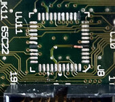
Thanks for your input. Attached is a photo of the UJ11 location where the blown chip has been removed. 3 of the connectors have been damaged (see photo) so I'm concerned I might not be able to solder a replacement chip should I find a dead Mac SE30 board ... Can it be fixed ?
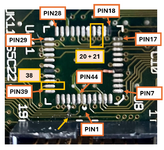
Whilst I found the schematic of UJ11 here, I'm looking for a way to read the real chip pin allocation on the board i.e. where shall I start reading pin 1 and next ones? I noticed all chips are surrounded by 3 perpendicular corners and a single diagonal corner. I guess the diagonal suggests to start reading pin 1 from the top but I'm not sure. If this is correct, the broken connectors are 16,33,40. On the previous schematics, I can see that 40 is connected to A10, I don't see anything with 33, and I'm not sure if 16 is the one next to Part of UH7 that goes to the disc drive port.

If I can't find a replacement chip, would it make sense to connect some connectors e.g. via a 10kΩ resistor to +5V (ex : 20, 21 for the read/write select lines, and 38 for SEL SWIM ?
If I remove the ROM & RAMs, should a regular/working Mac SE 30 boot fine without the horizontal lines ? I'm getting lines with or with them.
 

Attachments

  • unnamed.jpg
    unnamed.jpg
    177.1 KB · Views: 24
Last edited:

billbucks

New Tinkerer
Oct 23, 2023
68
13
8
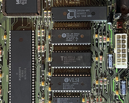
Someone suggested I could reuse the IWM chip from a Mac SE board (see photo) which I have.
Could it work ?

The corresponding pins could be determined from each board's schematics I guess.
 

Attachments

  • macseiwm.png
    macseiwm.png
    150.9 KB · Views: 10

JDW

Administrator
Staff member
Founder
Sep 2, 2021
1,815
1,545
113
54
Japan
youtube.com
You would need the newer SWIM chip, not IWM, because you are using an SE/30. @Kai Robinson created a PLCC-to-DIP adapter in the past, but it was never publicly released. However, you would need the opposite of that — a DIP-to-PLCC adapter. That would be rather awkward to solder on, even if it existed.

@Kay K.M.Mods has his own PLCC to DIP adapter here:

But again, you need the opposite of that, unfortunately.
 

billbucks

New Tinkerer
Oct 23, 2023
68
13
8
My intent is to remove the error screen and not use the floppy drive on the Mac SE30. If I use the IWM, could it solve this issue i.e. will the Mac SE30 be ok ?
I saw @Kay K.M.Mods project which is useful to identify the matching pins between both chips. Shouldn't it be feasible with a DIP28 and soldered wires to build a one-off custom solution ?
 

JDW

Administrator
Staff member
Founder
Sep 2, 2021
1,815
1,545
113
54
Japan
youtube.com
The difference between a "SWIM" and "IWM" is very important for the SE/30. As I said in my previous post, you need a SWIM, not an IWM chip.

So long as you have a SWIM chip and not an IWM chip, then it is merely a matter of figuring out how to wiring it properly to your motherboard, without making any pin wiring mistakes. But if connected properly, a DIP SWIM chip or a PLCC edition SWIM would work in your SE/30 motherboard.

But like I said, no one has a dummy-proof PCB solution for what you are seeking, which is to put a DIP SWIM onto PLCC SWIM pads (on an SE/30 motherboard).

And as I mentioned via PM, I am still waiting for a reply from the person I asked regarding your case. And I needed to ask because I have run out of ideas. You see, I've never had an issue with that chip, nor have a I tried to run an SE/30 board without the SWIM, so I cannot say what should happen when the chip is removed. I have been hoping someone else would jump into this thread and offer ideas, but thus far such has not happened.
 

billbucks

New Tinkerer
Oct 23, 2023
68
13
8
Thanks for your feedback.
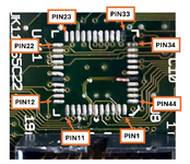
The suggestion I got won't work so I'll look for a SWIM replacement unless I figure out how to wire some UJ11 pins to remove the error (these schematics can be useful). Attached is my understanding of the SWIM pinout ; is it correct ?
 

Attachments

  • swimpins.png
    swimpins.png
    181.5 KB · Views: 13

JDW

Administrator
Staff member
Founder
Sep 2, 2021
1,815
1,545
113
54
Japan
youtube.com
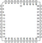
Incorrect.
Pin-1 is marked on the PCB and on the chip itself with a dot, and it should follow this diagram:

1742382577440.png


You also need to verify if the trace I've circled is broken, because it looks that way. It must not be broken.

1742381910490.png
 

Attachments

  • 1742382460288.png
    1742382460288.png
    26.8 KB · Views: 11
  • Like
Reactions: billbucks