Hey all!
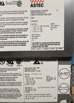
I have been collecting some old Macs the last couple of years, a Macintosh Plus, a Powerbook 170, a Macintosh IIvx, and a Quadra 700. All of them came to me working but needing either maintenance work like recapping, or in the case of the Powerbook, plastic repair. So I'd say I'm fairly confident in general repair work and soldering, without really knowing too much about electronics. Recently I picked up a Macintosh IIci that came to me not working. The power supply was dead and there was signs of minor capacitor leakage on the logic board. Having had success with my other Macs I was confident I could get this one working, so I set about cleaning up any corrosion I could see and recapping the board. Since I have a Quadra 700 I decided to use its PSU for the time being, beofre spending time recapping the one in the IIci.
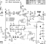
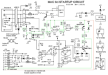
Having done all the work, I plugged the IIci in and...nothing. No errors, no beeps, no nothing. The fan on the PSU doesn't in try to spin up. At this point I'm pretty lost. From what I've read it seems my first go to should be the power circuit on the logic board, but I'm still not sure what the entails. Long story short, I'm hoping someone can give some pointers or guide me to what I should be trying and in what order to see if the board is indeed repairable with my limited skill set.
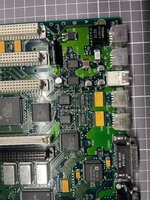
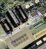
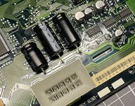
I'd upload a picture of the whole board but honestly the damage is almost imperpectible to the naked eye, but I can definetely try and take some macro photos if anyone wants to see a specific part of the board.
Any help appreciated, thanks!
I have been collecting some old Macs the last couple of years, a Macintosh Plus, a Powerbook 170, a Macintosh IIvx, and a Quadra 700. All of them came to me working but needing either maintenance work like recapping, or in the case of the Powerbook, plastic repair. So I'd say I'm fairly confident in general repair work and soldering, without really knowing too much about electronics. Recently I picked up a Macintosh IIci that came to me not working. The power supply was dead and there was signs of minor capacitor leakage on the logic board. Having had success with my other Macs I was confident I could get this one working, so I set about cleaning up any corrosion I could see and recapping the board. Since I have a Quadra 700 I decided to use its PSU for the time being, beofre spending time recapping the one in the IIci.
Having done all the work, I plugged the IIci in and...nothing. No errors, no beeps, no nothing. The fan on the PSU doesn't in try to spin up. At this point I'm pretty lost. From what I've read it seems my first go to should be the power circuit on the logic board, but I'm still not sure what the entails. Long story short, I'm hoping someone can give some pointers or guide me to what I should be trying and in what order to see if the board is indeed repairable with my limited skill set.
I'd upload a picture of the whole board but honestly the damage is almost imperpectible to the naked eye, but I can definetely try and take some macro photos if anyone wants to see a specific part of the board.
Any help appreciated, thanks!