Hello all!
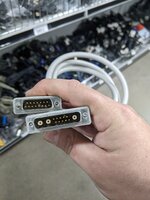
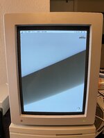
I posted this on 68kMLA and thought it might be worth posting here as well. I acquired a Macintosh Portrait Display from a warehouse in Houston that had been there for possibly (probably) years, so I was not expecting it to outright work after being in the coastal Texas heat and humidity for so long. Got it home and wired up a test cable to get the following:
Another local retro-computer user here in DFW also had one with similar issues (no pulsing, but the same smearing problem), and his was in much better shape than mine, so I thought it might very well just be aged caps. The high voltage and signal processing seemed okay (it was, after all, displaying an image with no sync/linearity issues), and the gain, brightness, sub-brightness, and contrast adjustments all affected the intensity of the problem(s). I'd never read anything about any common component failures in these, so caps seemed like a good place to start.
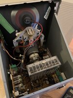
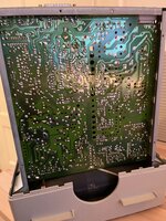
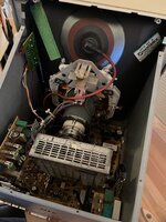
I started with recapping the power/sweep PCB, thinking that something might be awry with the circuitry driving the CRT. There were 35 caps to replace on the power/sweep board but, ultimately, none of them were directly responsible for the issue; still, this will go a long way to keep this thing alive. Next were the caps on the video signal board. There were 31 in total and this thing was much easier to work on than the other PCB. For one thing, it was about the size of a DVD case (the sweep board is about 10" by 12"); for another, it had no large or protruding components, which made it very easy to position when soldering new caps in place. Once everything had been replaced, back in it went and... everything was working great! The image is stable (with a tiny little amount of pincushion that I can iron out later) and has no artifacts, smearing, etc. In retrospect, I should have probably suspected the video board first and foremost; as I mentioned earlier, adjustments to the contrast, gain, bias, and sub-brightness controls directly affected the smearing and pulsing as seen in the video. I feel kind of dumb for not catching that sooner.
Below is a table of the caps on each board and their values; additionally, I've also put together a Mouser project link for the caps I used - hopefully some of this may be useful to someone some day!
Mouser Project
I posted this on 68kMLA and thought it might be worth posting here as well. I acquired a Macintosh Portrait Display from a warehouse in Houston that had been there for possibly (probably) years, so I was not expecting it to outright work after being in the coastal Texas heat and humidity for so long. Got it home and wired up a test cable to get the following:
Another local retro-computer user here in DFW also had one with similar issues (no pulsing, but the same smearing problem), and his was in much better shape than mine, so I thought it might very well just be aged caps. The high voltage and signal processing seemed okay (it was, after all, displaying an image with no sync/linearity issues), and the gain, brightness, sub-brightness, and contrast adjustments all affected the intensity of the problem(s). I'd never read anything about any common component failures in these, so caps seemed like a good place to start.
I started with recapping the power/sweep PCB, thinking that something might be awry with the circuitry driving the CRT. There were 35 caps to replace on the power/sweep board but, ultimately, none of them were directly responsible for the issue; still, this will go a long way to keep this thing alive. Next were the caps on the video signal board. There were 31 in total and this thing was much easier to work on than the other PCB. For one thing, it was about the size of a DVD case (the sweep board is about 10" by 12"); for another, it had no large or protruding components, which made it very easy to position when soldering new caps in place. Once everything had been replaced, back in it went and... everything was working great! The image is stable (with a tiny little amount of pincushion that I can iron out later) and has no artifacts, smearing, etc. In retrospect, I should have probably suspected the video board first and foremost; as I mentioned earlier, adjustments to the contrast, gain, bias, and sub-brightness controls directly affected the smearing and pulsing as seen in the video. I feel kind of dumb for not catching that sooner.

Below is a table of the caps on each board and their values; additionally, I've also put together a Mouser project link for the caps I used - hopefully some of this may be useful to someone some day!
Mouser Project
| Chassis (Sweep Board) | Signal Board | Neck Board |
C921: 470uF 10v C926: 100uF 16v C918: 3300uF 16v C722: 33uF 16v C740: 100uF 16v C919: 1000uF 16v C670: 47uF 16v C663: 22uF 16v C743: 1000uF 16v C624: 10uF 16v C718: 10uF 25v C917: 1000uF 25v C927: 22uF 25v C623: 10uF 25v C604: 1000uF 25v C923: 4.7uF 50v C734: 1uF 50v C924: 1000uF 50v C621: 47uF 50v C612: 100uF 50v C742: 1uF 50v C601: 1uF 50v C704: 1uF 50v C706: 220uF 50v C909: 47uF 100v C905: 10uF 100v C914: 220uF 100v C915: 220uF 100v C924: 47uF 100v C916: 100uF 100v C622: 4.7uF 100v C710: 220uF 100v C653: 1uF 100v C717: 4.7uF 250v C100: 330uF 400v | C322: 100uF 10v C302: 100uF 10v C356: 220uF 10v C326: 33uF 16v C310A: 470uF 16v C310B: 470uF 16v C32: 47uF 16v C30: 100uF 16v C301: 100uF 16v C334A: 470uF 16v C334B: 470uF 16v C332A: 470uF 16v C332B: 470uF 16v C307: 10uF 16v C325: 33uF 16v C327: 10uF 16v C304: 10uF 16v C36: 100uF 16v C503: 47uF 16v C506: 100uF 16v C313A: 470uF 16v C313B: 470uF 16v C316: 470uF 16v C312: 100uF 16v C308: 100uF 16v C513: 47uF 16v C510A: 4.7uF 250v C510B: 4.7uF 250v C505A: 4.7uF 250v C505B: 4.7uF 250v C331: 4.7uF 250v | C353: 47uF 16v C349: 33uF 100v C507: 33uF 100v C321: 4.7uF 160v C508: 4.7uF 250v C330: 4.7uF 250v |
Last edited:

