MacSD - Multi-device SCSI adapter with audio

retr01

Senior Tinkerer
Jun 6, 2022
2,473
1
794
113
Utah, USA
retr01.com
Cutting away the fan grille on the floor shield of the case could reduce noise further, but it's barely audible to begin with.

If the metal grille of the bottom shield rattled, then that would be a good idea. 🙂

The air still takes the same path in and out of the case. It just isn't firing straight up into the cover as it did before the mod.

Now, that is awesome! 👏😁
 

JDW

Administrator
Staff member
Founder
Sep 2, 2021
1,566
1,365
113
53
Japan
youtube.com
The glue can be broken if you put the CPU in the freezer for a while. Then scrape off any residue with a razor.

The recommended drying time is 24 hours, so I kept it clamped for that long.

Thermal glue
Thermal paste

The 100mm version should work great on your 040, especially if you can center it better than I could on the LC475.

Thanks for the kind words. They're especially appreciated, coming from someone of your experience.

@YMK
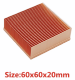
I don't mean to get too off topic here, but your earlier post really got me thinking hard about making the "pure copper heatsink" plunge, so I bought this 60x60x20mm heatsink last night:

The rather large 60mm size will barely fit onto an LC575 motherboard with IIe Card installed. It's 20mm tall too, which means my 40x10mm noctua fan can't be installed on top, which is terribly unfortunate. Another sad fact is that my 40mm Noctua fan would be too tall to stand it its side. As a result, I am mulling the purchase of one or two of these 12V 25x10mm fans, which in theory could be made to stand in their sides, and I guess affixed to some of the motherboard chips with some strong 2-sided tape:

I was able to find the exact glue you use on Amazon Japan here:

But instead of using that glue, @Mr. Fahrenheit got me thinking about a solution he used recently. Yes, this idea was presented to me in a "private email" but I doubt he'll mind me sharing this "magic secret" to the world. If he does, he can report my post. 🤣 (Yes, I'm poking fun at something that happened recently in another thread.)

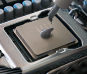
The Magic Cooling Secret™®© that Mr. F. used is to cut 4 thin strips of 2-sided thermal tape and place them all around the heatsink edges like this:
1665537281683.png

Mr. F. told me he then put a drop of good thermal paste in the middle.

The only thing I don't know is precisely how big of a drop to use, because if you use too little, it won't make for a good thermal transfer. And if your drop of paste is too big, then when you press down, paste will shoot past the tape in places, which will make most or all of the tape not stick as well as it should.

Another consideration is that when I paste something, I tend to use the X-method rather than a Drop because a drop will make a circle while an paste strewn out in the shape of an X will press into a square (which is best in terms of more complete coverage).

Naturally, the purpose of the tape is the same as the purpose of the glue you used -- to hold the heatsink atop the CPU, since it cannot be clipped or screwed down. And because I've got a lot of that blue MADE IN CHINA thermal tape, I am considering that tape instead of the glue. However, on the Amazon USA website, I find additional data on the glue you used...

Thermal conductivity > 1.2W/m-K

I believe the blue MADE IN CHINA thermal tape is a bit less than that, but not a whole lot less, I don't think. So perhaps it wouldn't matter whether one used glue or tape. Most of the heat transfer will come from the good thermal paste in the middle anyway.

The big benefit of the tape for me, other than already having a lot in my inventory, is that there is no drying time required, unlike the glue.

Any thoughts?
 
  • Love
Reactions: retr01

retr01

Senior Tinkerer
Jun 6, 2022
2,473
1
794
113
Utah, USA
retr01.com
The Magic Cooling Secret™®© that Mr. F. used is to cut 4 thin strips of 2-sided thermal tape and place them all around the heatsink edges like this:

9273-b3e24ee52e20d9caa587d56a1896b57f.jpg


Mr. F. told me he then put a drop of good thermal paste in the middle.

I have the same curiosity for my pizza box Mac. (Shhh! I'll post a thread about my newest addition to my Mac collection soon). :)
 

YMK

Active Tinkerer
Nov 8, 2021
358
285
63
The thermal conductivity figure has thickness factored out of it, since it's /m-K. If the paste and tape had the same rating and the paste allows a layer one quarter the thickness of the tape (which is a good bet), it will have a quarter of the absolute resistance. I don't think you'll find a favorable opinion of any thermal tape in overclocking circles.

Also, the thickness of the tape will increase the clearance between the CPU and heatsink, making the paste perform worse than it would alone. Don't be deterred by the glue's drying time. Leave it clamped overnight and it's good to go.

Instead of the two 25mm fans, I'd use a blower next to the heatsink if you have room for it:

That will require a custom shroud or duct to guide the air through the side of the heatsink, but it will move more air with less noise.
 
  • Like
Reactions: retr01

retr01

Senior Tinkerer
Jun 6, 2022
2,473
1
794
113
Utah, USA
retr01.com
I'd use a blower next to the heatsink if you have room for it:

That will require a custom shroud or duct to guide the air through the side of the heatsink, but it will move more air with less noise.

I like the idea of using a centrifugal fan instead of two regular fans—more CFM for more air circulation. The Noctua fan takes care of the flyback's heat, and the centrifugal fan cools down the CPU. :)
 

JDW

Administrator
Staff member
Founder
Sep 2, 2021
1,566
1,365
113
53
Japan
youtube.com
...the thickness of the tape will increase the clearance between the CPU and heatsink, making the paste perform worse than it would alone.
Instead of the two 25mm fans, I'd use a blower next to the heatsink if you have room for it:
Clearly, you are saying that using the glue is better than the tape because the glue will flatten out as much as the thermal paste will, thereby ensuring the tape doesn't rise up higher than the past in the middle. Understood!

Sadly, there is no room for such a blower, as you can see from this photo of my board (without the IIe Card installed)...

1665543563607.png


Any fan used would need to be placed where the battery wires connect to the logic board, which is also where Spicy O'Clock connects its black & red wires to that IC on the motherboard. I 25x10mm fan stood up on its side might barely fit there. I don't know. But certainly not a big fan.
 

YMK

Active Tinkerer
Nov 8, 2021
358
285
63
What about changing the battery header to right angle and running the blower exhaust over it?

It looks like the caps and oscillator are below the top of the 040, where the duct would go.
 

JDW

Administrator
Staff member
Founder
Sep 2, 2021
1,566
1,365
113
53
Japan
youtube.com
What about changing the battery header to right angle and running the blower exhaust over it?
It looks like the caps and oscillator are below the top of the 040, where the duct would go.
While that can be done, we must consider the inductive fan load. It would run right up against Spicy O'Clock, and over its wires. That is what allows me to overclock the CPU as high as 50MHz. So long as the fan doesn't induce any electrical noise into the overclocker lines, then it might work.

But I had to move my white PRAM battery holder to a different location than is shown in my previously posted photos. The IIe Card mounts there, so I had to move it on top of the big chip shown here...

1665548900759.png
 

YMK

Active Tinkerer
Nov 8, 2021
358
285
63
I don't think a fan will be radiating much EMI, but a 50 (or 100) MHz signal on a lone wire could be.

A twisted pair or shielded cable might be a good idea there.
 

JDW

Administrator
Staff member
Founder
Sep 2, 2021
1,566
1,365
113
53
Japan
youtube.com
Don't be deterred by the glue's drying time. Leave it clamped overnight and it's good to go.
With it getting closer to the time my copper heatsink will arrive, I wanted to check with you about the amount of thermal paste and glue you used, and the precise means of clamping.

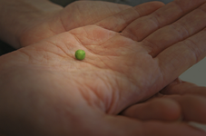
Did you put a green-pea sized drop of paste in the very center of the CPU, then apply a half-pea size drop at each of the outer 4 corners of the CPU?

1666332476920.png

By pea-size, I mean something similar to this amount...

1666331648473.png

Also, precisely how did you clamp it? Did you remove the CPU, put some foam on the pin side (to prevent pins from making contact with the clamp, then use a metal clamp to press the heatsink down on the CPU for 24 hours? And how did you determine the best clamping pressure?

Lastly, is the glue you used so strong that there is no worry of it cracking or weakening when you then press the CPU/Heatsink combo into the socket? And what about later removal of the CPU? Is the glue strong enough to allow you to remove the CPU by grabbing and pulling up on the heatsink?

On my LC575 board currently, I need to use a small flat-head screwdriver to slowly lift the CPU out of the socket, using the screw-driver on all 4 sides. But with a 60mm heatsink installed on top of the 45mm CPU, I would need to grab the heatsink and wiggle that to get the CPU out (or break off the heatsink).

This is the shape and size of the pure copper heatsink I purchased...

1666331946833.png
 

YMK

Active Tinkerer
Nov 8, 2021
358
285
63
Did you put a green-pea sized drop of paste in the very center of the CPU, then apply a half-pea size drop at each of the outer 4 corners of the CPU?

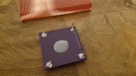
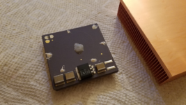
I've varied the amount. This 040 is on the heavy side and the paste was pressed out along every edge:
1666339539211.png

I bought the 80x80x20 version for a Pentium 83. I used less paste for this, maybe too little. It reached two of the edges (as shown in the clamp picture) so I figure it's mostly covered. This CPU will be duct-cooled. I'll post more about this machine when it's done.

1666339693803.png

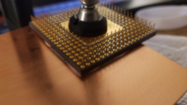
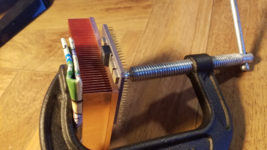
I used a C-clamp to apply pressure, so the pins don't bear any load. It's not difficult to generate hundreds of pounds of force with these clamps, so "finger-tight" is adequate.

1666339912303.png

The CPU side of this clamp has a rubber boot so it won't scratch the CPU. I folded up some cardboard on the other side to avoid bruising the fins.

1666340190964.png


Lastly, is the glue you used so strong that there is no worry of it cracking or weakening when you then press the CPU/Heatsink combo into the socket? And what about later removal of the CPU? Is the glue strong enough to allow you to remove the CPU by grabbing and pulling up on the heatsink?

Yes, I can install and remove the CPU by pushing and pulling on the heat sink - no more prying. :) The flip side of that is, there's a risk of the CPU coming loose if the machine is shipped.

Before gluing, to ease future heat sink removal, you can drill a ~4mm hole or depression in the heat sink, centered on the edge of where the CPU will be. That will give you a pry point for a flat head screwdriver. Freeze to split the heat sink and CPU, then use hot air and a razor on any glue residue.

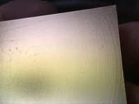
Also, if your heat sink is like mine it has a machined "grain" to it. You can tell by running your fingernail across it. If you're looking for the best possible cooling performance, lapping/polishing might be worthwhile.
 
Last edited:
  • Love
  • Like
Reactions: Patrick and JDW

JDW

Administrator
Staff member
Founder
Sep 2, 2021
1,566
1,365
113
53
Japan
youtube.com
@YMK
Thank you for the photos and detailed info.

Does "finger tight" mean "as far as it will turn when twisting with all your might" or "turn it just to the point when it gets a little hard to turn?"

My heatsink arrived this evening, and my goodness it's quite heavy!


Yes, it is very finely machined on the bottom. Not sure why they chose to do that instead of making it smooth.

tempImagepOOdI6.png

Not sure how best to polish that out, or if fine steel wool would just make a mess of it. Might be best for me to leave it as is.

Do you know what the equivalent of your clamp is on Amazon.com? I found this C-clamp on Amazon Japan that might work, but they don't put down the width of the round piece...

1666359199989.png


Based on that picture, the round piece looks to be about 30mm wide. Not sure what the width of that central square area is (area with no pins) on the underside of a 68040, so I'll need to pull the CPU on Monday to measure and find out. Anyway, the nice thing about that C-clamp I found on Amazon Japan is that it's rubber coated on the round piece and the opposite piece you clamp against.
 

YMK

Active Tinkerer
Nov 8, 2021
358
285
63
Based on that picture, the round piece looks to be about 30mm wide.

30mm is about the limit for an 040. Any bigger and you'll have to make a spacer of some kind to clear the pins. Better to choose a smaller clamp.

Does "finger tight" mean "as far as it will turn when twisting with all your might" or "turn it just to the point when it gets a little hard to turn?"

This is going to vary based on the length of the handle and the pitch of the screw.

Roughly, it means the force you can exert with your thumb and fingers, without putting much wrist or arm into it.

Increase the force slowly in steps, repositioning the CPU as it drifts. When you have enough force and excess paste is squeezed out, it won't wiggle around anymore.

Not sure how best to polish that out, or if fine steel wool would just make a mess of it. Might be best for me to leave it as is.

One way is a flat surface like glass or marble and wet sandpaper of increasing grit (400, 1000, 2000).

Another way is a foam sanding block with light pressure.

I wouldn't recommend sanding freehand because you risk worsening the flatness, which defeats the purpose.
 

François

Tinkerer
Aug 9, 2022
90
39
18
France
Yes, it is very finely machined on the bottom. Not sure why they chose to do that instead of making it smooth.

tempImagepOOdI6.png

Not sure how best to polish that out, or if fine steel wool would just make a mess of it. Might be best for me to leave it as is.
No need to smooth it out, I think, the thermal paste will fill the grooves.
 

YMK

Active Tinkerer
Nov 8, 2021
358
285
63
No need to smooth it out, I think, the thermal paste will fill the grooves.

It will, but the heat sink won't perform as well as one with a flatter surface.

Thermal compound doesn't have the conductivity of copper.
 

retr01

Senior Tinkerer
Jun 6, 2022
2,473
1
794
113
Utah, USA
retr01.com
Hey @JDW! :)

I found the force exerted by tightening the fingers without any tool or leverage or using the wrist or arm. The screw or nut tightened using the fingers, and no tools, to a torque of about 1.7 to 2.3 Nm. That measure of the force that can cause an object to rotate about an axis is about twice the feeling of weight when someone places an apple in your hand that you stretch out with a straight arm. So, not "all with your might," as it is turning "just to the point when it gets a little hard to turn."
 
Last edited:

YMK

Active Tinkerer
Nov 8, 2021
358
285
63
I found the force exerted by tightening the fingers without any tool or leverage or using the wrist or arm.

The handle on the C-clamp provides the leverage, but that's one of many variables.

The torque will be much higher than turning a nut by hand.
 
  • Like
Reactions: retr01