My little guide on RGBTOHDMI installed on Classic, Plus, etc.

Mu0n

Active Tinkerer
Oct 29, 2021
609
560
93
Quebec
www.youtube.com
Here are the settings in text form for the SE/30

Mac SE/30:
Geometry:
Setup Mode: normal
H Offset: 176
V Offset: 28
Min H Width: 512
Min V Height: 342
Max H Width: 512
Max V Height: 342
H Pixel Aspect: 2
V Pixel Aspect: 2
FB Size: Normal
FB Bits/Pixel: 8
Clock Frequency: 15667200
Line Length: 704
Clock Tolerance: 5000
Lines per Frame: 370
Sync Type: +H+V
V Sync Type: Auto
Video Type: Progressive

Sampling Menu:
Setup Mode: normal
Sampling Phase: 5 (300 Degrees)
Half Pixel Shift: Off
Clock Multiplier: x6
Calibration Range: Auto
Pixel H Offset: 7
Sync Edge: Trailing
Sync on G/V: Off
Sample Mode: 3 bits per Pixel

and in the palette I had to go invert the colors and choose an appropriate border color that showed as black.

1693829275798.png


1693829726022.png


1693829749074.png

1693829795922.png
 

Mu0n

Active Tinkerer
Oct 29, 2021
609
560
93
Quebec
www.youtube.com
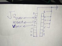
Here are the pins used on the Mac SE/30 J12 connector, seen from ABOVE the board. Pay close attention, the four corners are marked with the silkscreen around the connector on the logic board.

(sept 8 edit made a better J12 connector (seen from above the logic board) diagram)
J12 on logic.png

1693826008400.png
 

Attachments

  • PXL_20230904_132236883.jpg
    PXL_20230904_132236883.jpg
    969.8 KB · Views: 101
Last edited:

Mu0n

Active Tinkerer
Oct 29, 2021
609
560
93
Quebec
www.youtube.com
I added a better image of where the cables go into the connector on the Plus which links the logic and analog board (J4 on the analog side); wires are inserted from above the logic board connector

1694661377924.png
 

CubeTheory

New Tinkerer
Oct 29, 2023
5
6
3
Hi, Great post. Just wanted to share my escapades. I built a few RGBtoHDMI's a while back but after recently getting my Classic back from a friend after about 17 years, and fully refurbishing it. I needed a way to test the logic board in isolation from the Analog board, which took some effort to get working!

I came up with this:

Using an Amiga PSU, which I had rebuilt using a Meanwell RPT-60b PSU which outputs +/-12v and +5v (My bench supply only has one output) I made a test harness so I could non-destructively remove the Amiga connector and fit the harness

IMG_4019.jpeg


IMG_4015.jpeg


I just needed to re-flash my RGBtoHDMI CPLD and then using the last distro select the classic profile which I did in isolation, so once all was connected it started straight up. the aspect ratio doesn't look right but based on this thread, I think I'll give it a tweak when I next remove the board.

IMG_4017-00-00-16-483.jpeg
 

lundpk

New Tinkerer
Dec 16, 2023
1
0
1
60
New Ulm, MN
blc.edu
I am considering doing a presentation of the Mac on its 40th anniversary at our college and wonder if the RGBtoHDMI will work on a restored 512K FatMac that I have in my office. This would make a tie into our projector for the presentation.
 

CubeTheory

New Tinkerer
Oct 29, 2023
5
6
3
Hi.

I found a guy selling them here in Brazil. But he got me confused (he’s not an Apple guy) about the version I should buy: digital or analog?

thanks.
The analog version will just be an additional board the plugs in, in between the Pi and the RGBtoHDMI pHat. you don’t need it for this but usually they are removable and are useful if you have other vintage machines with analog RGB outputs.

it is recommended to have the TTL buffer board which, again, would go in between the Pi and the RGBtoHDMI pHat, replacing the analog board, but it is just for protecting the CPLD. I don’t have one and haven’t had any issues, though your mileage may vary

This is an analog board
IMG_1241.jpeg

IMG_1242.jpeg
 
  • Like
Reactions: Genjoke
I bought an assembled RGBtoHDMI from TexElec to use with a Mac Plus. After making a cable (using @Mu0n 's instruction video) and connecting it up inside the Plus. It all seemed to be kind of working, but I wasn't getting a good picture on the HDMI end. I installed the latest firmware (20240213_e630d36f), thinking that might help. Things were still not working right. The picture never looked quite right, it wouldn't show me any profiles, wouldn't save settings, and eventually wouldn't boot from the SD card at all.

Long story short, when I had reformatted the SD card on my Mac (erasing the firmware it came with in order to install the new firmware), I should have done a full erase. Once I did that, it all worked.

The new firmware is great. I could select the Mac 128-512-Plus profile and it just worked. No need to mess with the various menu settings. The only thing I had to change was the scaling, so it would display in the proper aspect, and not stretched to fill the wide screen display.
 
Last edited:
  • Like
Reactions: Mu0n and fred1212

Mu0n

Active Tinkerer
Oct 29, 2021
609
560
93
Quebec
www.youtube.com
I walked back my true and tested method of shove-Dupont-M-wire-end-into-J12-socket for my SE/30 and got myself a J12 passthrough from jcm-1.com hosted by Joe, designed by @Ron's Computer Videos.


The IDC connector at the side of it is perfectly tailor made for Dupont F ends and like always, only uses 4 pins.

1720450390438.png


being keyed, the passthrough can only go in the right way and is very friendly to letting you put back the logic board in the chassis. It even makes it easier to plug in/plug out the J12 cable into this newly raised socket at the top of the passthrough.

What prompted me to use this is that one time when I opened up my case and moved the logic board around, I accidently disconnected a RGBtoHDMI wire that was shoved into the J12 socket. Not having a "real" secure method for your cables is possible, but it adds verification steps every time you must open or close. It was painless to add this cheap socket to my jcm-1 order (I was in the market for a v2 picogus and various cell battery holders).

1720450695617.png


The connections are marked with silkscreen on the board near some through holes (which I elected to not use because I'm a dupont cable fan), but not near the IDC connector. After a few minutes spent with a multimeter in continuity mode, you learn which of the pins are relevant, so here's a small chart for your convenience. You may use your preferred GND pin that strikes your fancy the best, of course.

1720451243494.png