My MacSD Upgrade for the Colour Classic [and Stereo Mod]

MacinJosh

Tinkerer
Jan 16, 2022
52
54
18
46
Finland
www.atariancomputing.com
So you put one 10kΩ resistor from the RED wire (Right) in your picture above to the BLK (GND), and then put another 10kΩ resistor from the WHT (Left) wire to BLK (GND), correct?

And previously, you had the two 10kΩ resistors inline with each of the RED & WHT wires (i.e., not going to GND), correct?
This is all correct. Neither method seemed to have any impact so I would hold off on doing it unless there is perceivable clipping or distortion which is what @YMK was saying all along.

I think I'll do the stereo mod this weekend and see if I get the extra options in the sound control panel after that to control the volume of the CD-audio.
 
  • Like
Reactions: YMK and JDW

MacinJosh

Tinkerer
Jan 16, 2022
52
54
18
46
Finland
www.atariancomputing.com
This is all correct. Neither method seemed to have any impact so I would hold off on doing it unless there is perceivable clipping or distortion which is what @YMK was saying all along.

I think I'll do the stereo mod this weekend and see if I get the extra options in the sound control panel after that to control the volume of the CD-audio.
@JDW I just did the stereo mod but I’m a little confused. While the new speaker is working, there is no stereo separation whatsoever and new speaker is more quiet as others have reported. Speaker is from a CC donor. Control panel shows no difference than what it was. Still mono. I’m sure I followed all instructions. Just to check, what instructions were you planning on following?
 
  • Like
Reactions: YMK

MacinJosh

Tinkerer
Jan 16, 2022
52
54
18
46
Finland
www.atariancomputing.com
Hmm... Not sure what's going on...

Sounds Control Panel indicates Stereo
Sounds.png


But Monitors & Sound doesn't look like it is...
Monitors & Sound.png


AppleCD Audio Player plays through all speakers even when selecting left or right. Am I missing something?

Anyway, as for the components, here are my findings:

CS1 is obviously a bypass cap, given its location. I still measured it to check my meter's accuracy; bang on 100nF
CS3 is an electrolytic 1µF 50v
CS5 is 3.2-3.3nF, not 3.3µF as has been stated in some guides.
RS1 is 5K1

I'm also getting slight popping sounds and interference now. Not sure I like this mod tbh...
 
  • Like
Reactions: YMK

Fizzbinn

Tinkerer
Nov 29, 2021
189
183
43
Charlottesville, VA
@JDW I just did the stereo mod but I’m a little confused. While the new speaker is working, there is no stereo separation whatsoever and new speaker is more quiet as others have reported. Speaker is from a CC donor. Control panel shows no difference than what it was. Still mono. I’m sure I followed all instructions. Just to check, what instructions were you planning on following?
Curious, what reference/guides are you using for the stereo mod? I found the following awhile back, ordered a TDA7052A Philips amp chip, but never went any further.

 
  • Like
Reactions: YMK

JDW

Administrator
Staff member
Founder
Sep 2, 2021
1,566
1,365
113
53
Japan
youtube.com
The stereo mode involves much, much more than just adding another speaker. It will take a long time for me to explain the procedure properly which is why I want to make a video on it. I simply thought you had found a place on the Internet that described all the parts that you need.

there’s actually still a lot more investigation and research on that mod before I embark upon explaining it to anyone else. I planned to do that in conjunction with Kay Koba because he’s done it before. i’m in the middle of creating my overclocking video right now, so I just don’t have time to talk to him about it, but maybe you could send him a PM.

 
  • Like
Reactions: YMK

YMK

Active Tinkerer
Nov 8, 2021
358
285
63
Curious, what reference/guides are you using for the stereo mod? I found the following awhile back, ordered a TDA7052A Philips amp chip, but never went any further.

Also curious, though with any Mac capable of stereo, I typically go with external speakers.
 

MacinJosh

Tinkerer
Jan 16, 2022
52
54
18
46
Finland
www.atariancomputing.com

JDW

Administrator
Staff member
Founder
Sep 2, 2021
1,566
1,365
113
53
Japan
youtube.com
@Fizzbinn @YMK - I used the Welcome to the Going Stereo page of the Colour Classic Compendium guide and http://colourclassicfaq.com/general/stereo.html, which has some issues in it.

@JDW I certainly am aware that the process is more complex than slapping on another speaker. I will ask Kay Koba but just to be clear, are you saying that his/your method is different than what is described in the links above?
I have been referencing that Stuart Bell / Alexey Danilchenko guide, which you can find still online (in addition to Archive.org) here:

As always, the processes we find online are short on details (e.g., what is CS2? CS6?), which has long been the inspiration for me to investigate further and ultimately make videos showing the details everyone should have been told from the get-go. But like I said, I am still very much in the process of gathering info right now because I am quite busy working on my Overlocking video at the moment, and after that, I absolutely MUST get the Kai Robinson SE Reloaded video out, after which I can think more seriously about the Stereo Mod.

For now, here is a copy/paste of my Notes on the process, which I compiled for my forthcoming video on that topic. But keep in mind that I have started nothing yet and I still need to consult Kay Koba about it to gather his first-hand experiences...

Required Parts:​
  • TDA7052A (source from LC575 analog board?)
  • 1µF 50V radial capacitor (same physical size as CS4 — measure)
  • CS2 equivalent capacitor (SMD) — desolder & measure
  • CS6 equivalent capacitor (SMD) — desolder & measure
  • RS4 equivalent resistor (SMD, 5.1kΩ, "512", 1/8W?)
  • Speaker with Enclosure (a cheap/junked Quadra/ LC 630 has a speaker identical to the CC!)
Procedure:​
  • Solder a TDA7052A into IS1 holes.
  • Solder a 1µF 50V cap at CS3 holes.
  • Desolder RS7 (104=100kΩ), then solder it on RS2 pads.
  • What is capacitor CS2? Solder its equivalent on to CS1 pads.
  • What is capacitor CS6? Solder its equivalent on to CS5 pads.
  • Solder a 5.1kΩ ("512") SMD resistor (same as RS4) on to RS1 pads.
  • At SS1 (component side marking), drill 2 small holes on the trace side at the place where the 3 pads are (similar to SS2) for the purpose of soldering in the 2 wires from your second Speaker (pulled from a Q630). Then twist the speaker wires and solder them.
Pasted Graphic.tiff
Pasted Graphic 1.tiff
 

MacinJosh

Tinkerer
Jan 16, 2022
52
54
18
46
Finland
www.atariancomputing.com
I have been referencing that Stuart Bell / Alexey Danilchenko guide, which you can find still online (in addition to Archive.org) here:

As always, the processes we find online are short on details (e.g., what is CS2? CS6?), which has long been the inspiration for me to investigate further and ultimately make videos showing the details everyone should have been told from the get-go. But like I said, I am still very much in the process of gathering info right now because I am quite busy working on my Overlocking video at the moment, and after that, I absolutely MUST get the Kai Robinson SE Reloaded video out, after which I can think more seriously about the Stereo Mod.

For now, here is a copy/paste of my Notes on the process, which I compiled for my forthcoming video on that topic. But keep in mind that I have started nothing yet and I still need to consult Kay Koba about it to gather his first-hand experiences...

Required Parts:​
  • TDA7052A (source from LC575 analog board?)
  • 1µF 50V radial capacitor (same physical size as CS4 — measure)
  • CS2 equivalent capacitor (SMD) — desolder & measure
  • CS6 equivalent capacitor (SMD) — desolder & measure
  • RS4 equivalent resistor (SMD, 5.1kΩ, "512", 1/8W?)
  • Speaker with Enclosure (a cheap/junked Quadra/ LC 630 has a speaker identical to the CC!)
Procedure:​
  • Solder a TDA7052A into IS1 holes.
  • Solder a 1µF 50V cap at CS3 holes.
  • Desolder RS7 (104=100kΩ), then solder it on RS2 pads.
  • What is capacitor CS2? Solder its equivalent on to CS1 pads.
  • What is capacitor CS6? Solder its equivalent on to CS5 pads.
  • Solder a 5.1kΩ ("512") SMD resistor (same as RS4) on to RS1 pads.
  • At SS1 (component side marking), drill 2 small holes on the trace side at the place where the 3 pads are (similar to SS2) for the purpose of soldering in the 2 wires from your second Speaker (pulled from a Q630). Then twist the speaker wires and solder them.

Ok thanks, it's the same guide as I followed. I did post my findings about the components a few posts back:

CS1 is obviously a bypass cap, given its location. I still measured it to check my meter's accuracy; bang on 100nF​
CS3 is an electrolytic 1µF 50v​
CS5 is 3.2-3.3nF, not 3.3µF as has been stated in some guides.​
RS1 is 5K1​
I checked with Kay Koba and he suggested I make sure the Gestalt ID is LC575 (it was) and try re-install the system, which is what I'm doing now.
 

MacinJosh

Tinkerer
Jan 16, 2022
52
54
18
46
Finland
www.atariancomputing.com
Ok, just an update.

The snapping and popping sound apparently is from a bad speaker wire (I assume) and I had a play session with Heroes of Might & Magic II and I could hear the glorious stereo sound coming and going with the pops. So stereo sound is definitively there. I just need to get myself to open the CC up for the millionth time...

As for the control panels and balance adjustments I assume should be there, I can't get them to appear. I have installed clean OS 8.1, clean OS 7.6, installed QT4 that comes with the latest Sound Manager extension. No difference. I'm expecting this:

1645431311311.png


But getting this:
1645431359161.png
 

JDW

Administrator
Staff member
Founder
Sep 2, 2021
1,566
1,365
113
53
Japan
youtube.com
Ok, just an update.

The snapping and popping sound apparently is from a bad speaker wire (I assume) and I had a play session with Heroes of Might & Magic II and I could hear the glorious stereo sound coming and going with the pops. So stereo sound is definitively there. I just need to get myself to open the CC up for the millionth time...

As for the control panels and balance adjustments I assume should be there, I can't get them to appear. I have installed clean OS 8.1, clean OS 7.6, installed QT4 that comes with the latest Sound Manager extension. No difference. I'm expecting this:

View attachment 3223

But getting this:
View attachment 3224

Sorry for my delayed reply. I've been dealing with a family medical emergency since the 21st, and it is still ongoing.

I've not tested this, but what happens if you install Wish I Were and set it to a Mac which supports that expanded Monitors & Sound control panel?
 

MacinJosh

Tinkerer
Jan 16, 2022
52
54
18
46
Finland
www.atariancomputing.com
Sorry for my delayed reply. I've been dealing with a family medical emergency since the 21st, and it is still ongoing.

I've not tested this, but what happens if you install Wish I Were and set it to a Mac which supports that expanded Monitors & Sound control panel?
Hi,

Very sorry to hear about the family medical emergency. I really wish the best outcome for it.

I've tried Wish I were, clean installs of various Mac OS versions, no extensions, and pretty much everything that I can think of. Nothing has an impact.
 

JDW

Administrator
Staff member
Founder
Sep 2, 2021
1,566
1,365
113
53
Japan
youtube.com
Hi,

Very sorry to hear about the family medical emergency. I really wish the best outcome for it.

I've tried Wish I were, clean installs of various Mac OS versions, no extensions, and pretty much everything that I can think of. Nothing has an impact.
@Kay K.M.Mods has done the stereo mod. Maybe he knows the secret to getting the full "Monitors & Sound" control panel to display in System 7.6 or 8.1?
 

JDW

Administrator
Staff member
Founder
Sep 2, 2021
1,566
1,365
113
53
Japan
youtube.com
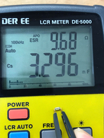
CS5 is 3.2-3.3nF, not 3.3µF as has been stated in some guides.
I wish we had a schematic of the CC Analog board! But that doesn't exist outside Apple's internal archives. (You'd think will all the leaking that goes on, someone would have leaked those schematics by now!)

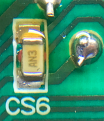
The web info on the Stereo Mod says to put the same capacitor on the CS5 pads as is used at CS6. Pretty funny too because none of those instructions state the capacitance or voltage specs! Well today I desoldered and then measured it...

1653977906200.png

1653978007725.png

So at 100kHz, it measures 3.3nF. But at 120Hz, it measured about 3.5nF. That's why a schematic would have been helpful to know what the intended value should be. Even so, we know the marking on the capacitor at CS6 is AN3. For the life of me, I cannot find a single photo of another cap with that marking, but I did find this...


It shows a table and how to use the table. They give an example of KA2 = 100pf (0.1nF). They say K=Kemet, and the "1" would be from the A, and the 2 zeros after the 1 would come from "2". Based on that, when pondering AN2, I can only guess A=AVX, and then we know N=3.3, and then 3 = "multiply by 1000". 3.3 x 1000 = 3300pF = 3.3nF. A table I found in a KEMET SMD Cap datasheet confirms that (when considering only the "N3" of "AN3")...

1653978944816.png


Next, I measured the body of CS6:

L = 3.2mm
W = 1.65mm

Which corresponds to 3216 (1206).

Small capacitance sizes in the low nF and pF range tend to use C0G/NP0, so I will guess CS6 uses that dielectric. Even if it doesn't, C0G is by far better than X7R or lesser grade ceramic caps (temperature stable and no voltage bias issues).


But to order a cap on Mouser or Digikey, you also need to know the Voltage & Tolerance specs. That's where we need to guess (because we have no schematic), A higher voltage spec and smaller tolerance value are safest, but go too extreme and the part price gets a bit high. Pricing all the 1% to 5% tolerance parts between 50V and 100V, leads me to guess that p/n: 12061A332JAT2A might be best for CS6 (5% tolerance, 100V). It's not going to be over 100V in that location, and 5% is a very tight tolerance.


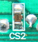
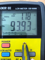
Next, is the capacitor needed for the CS1 pads. The info on the net says, "same cap as CS2." I desoldered and measured CS2...

1653980414806.png

1653980476792.png

Marking is IA5, which means I=manufacturer (who knows!), A5 = 100,000pF = 100nF = 0.1uF. This is a bypass cap, mostly likely an X7R.

Choosing Voltage & Tolerance requires the same guesswork as with CS6, but in my case, since I have stock of Vishay p/n: VJ1206Y104KXACW1BC (50V, 10% tolerance, body size 3216/1206), I will use that on the CS1 pads.


I will comment on the other required parts when I have more time. I'm still in the middle of the SE Reloaded project filming, and after that I made promises to do a video on BlueSCSI and MacSD, but after that, I will do the Stereo mod.
 
  • Love
Reactions: Kai Robinson

JDW

Administrator
Staff member
Founder
Sep 2, 2021
1,566
1,365
113
53
Japan
youtube.com
...ordered a TDA7052A Philips amp chip, but never went any further.
Where did you order it from? Do you have a photo of the chip you bought?

This makes me curious about SOURCING.

I see one on EBAY for a cheap price and with nice markings, but two questions arise:

1. Is that photo of the real chip, but you will receive something very different?
2. If the photo is of the chip you will get, is it authentic or a fake?
3. Do fake chips work as well as the original chips?

Only the SMD type chips are made. The DIP has been out of production for years. The DIP is far, far better because you get 1W out of it. You can't do that with the SMD chips.

@Kay K.M.Mods told me I could extract one from my LC575 (which I purchased for the purpose of using its motherboard in my CC. But not everyone has the 575 to do that. Kay, where do you source those chips?
 

Fizzbinn

Tinkerer
Nov 29, 2021
189
183
43
Charlottesville, VA
Where did you order it from? Do you have a photo of the chip you bought?

This makes me curious about SOURCING.

I see one on EBAY for a cheap price and with nice markings, but two questions arise:

1. Is that photo of the real chip, but you will receive something very different?
2. If the photo is of the chip you will get, is it authentic or a fake?
3. Do fake chips work as well as the original chips?

Only the SMD type chips are made. The DIP has been out of production for years. The DIP is far, far better because you get 1W out of it. You can't do that with the SMD chips.

@Kay K.M.Mods told me I could extract one from my LC575 (which I purchased for the purpose of using its motherboard in my CC. But not everyone has the 575 to do that. Kay, where do you source those chips?

I ordered this from eBay:
As I've yet to use it, I can't comment on how it works but the seller says the right things and has 100% positive feedback...
 
Last edited:
  • Like
Reactions: JDW

JDW

Administrator
Staff member
Founder
Sep 2, 2021
1,566
1,365
113
53
Japan
youtube.com
I order this from eBay:
As I've yet to use it, I can't comment on how it works but the seller says the right things and has 100% positive feedback...
Thanks for sharing. Hopefully the chip is authentic, because the price (without shipping) is just under $10.

That seller in Florida is great for folks in the US (if the chip is genuine), but shipping fees make it a bad deal overall for those overseas...

1654058547896.png


And that's really why most people will wonder which chips are genuine and which are fake, since shipping charges make one lean toward the lower cost items, especially if the top chip markings match the original chip.

I'm still a long way off from doing the Stereo Mod video, but I'm making some preparations for it now, hence my questions and measurement data.
 

Kai Robinson

TinkerDifferent Board President 2023
Staff member
Founder
Sep 2, 2021
1,158
1
1,171
113
42
Worthing, UK
I wish we had a schematic of the CC Analog board! But that doesn't exist outside Apple's internal archives. (You'd think will all the leaking that goes on, someone would have leaked those schematics by now!)

The web info on the Stereo Mod says to put the same capacitor on the CS5 pads as is used at CS6. Pretty funny too because none of those instructions state the capacitance or voltage specs! Well today I desoldered and then measured it...

View attachment 5375

View attachment 5376

So at 100kHz, it measures 3.3nF. But at 120Hz, it measured about 3.5nF. That's why a schematic would have been helpful to know what the intended value should be. Even so, we know the marking on the capacitor at CS6 is AN3. For the life of me, I cannot find a single photo of another cap with that marking, but I did find this...


It shows a table and how to use the table. They give an example of KA2 = 100pf (0.1nF). They say K=Kemet, and the "1" would be from the A, and the 2 zeros after the 1 would come from "2". Based on that, when pondering AN2, I can only guess A=AVX, and then we know N=3.3, and then 3 = "multiply by 1000". 3.3 x 1000 = 3300pF = 3.3nF. A table I found in a KEMET SMD Cap datasheet confirms that (when considering only the "N3" of "AN3")...

View attachment 5377

Next, I measured the body of CS6:

L = 3.2mm
W = 1.65mm

Which corresponds to 3216 (1206).

Small capacitance sizes in the low nF and pF range tend to use C0G/NP0, so I will guess CS6 uses that dielectric. Even if it doesn't, C0G is by far better than X7R or lesser grade ceramic caps (temperature stable and no voltage bias issues).


But to order a cap on Mouser or Digikey, you also need to know the Voltage & Tolerance specs. That's where we need to guess (because we have no schematic), A higher voltage spec and smaller tolerance value are safest, but go too extreme and the part price gets a bit high. Pricing all the 1% to 5% tolerance parts between 50V and 100V, leads me to guess that p/n: 12061A332JAT2A might be best for CS6 (5% tolerance, 100V). It's not going to be over 100V in that location, and 5% is a very tight tolerance.


Next, is the capacitor needed for the CS1 pads. The info on the net says, "same cap as CS2." I desoldered and measured CS2...

View attachment 5378

View attachment 5379

Marking is IA5, which means I=manufacturer (who knows!), A5 = 100,000pF = 100nF = 0.1uF. This is a bypass cap, mostly likely an X7R.

Choosing Voltage & Tolerance requires the same guesswork as with CS6, but in my case, since I have stock of Vishay p/n: VJ1206Y104KXACW1BC (50V, 10% tolerance, body size 3216/1206), I will use that on the CS1 pads.


I will comment on the other required parts when I have more time. I'm still in the middle of the SE Reloaded project filming, and after that I made promises to do a video on BlueSCSI and MacSD, but after that, I will do the Stereo mod.
That lookup table is just what i was searching for! :)
 
  • Love
Reactions: JDW

JDW

Administrator
Staff member
Founder
Sep 2, 2021
1,566
1,365
113
53
Japan
youtube.com
I ordered this from eBay:
As I've yet to use it, I can't comment on how it works but the seller says the right things and has 100% positive feedback...
You must have received your chip from EBAY by now. Does what you received look like the EBAY photo? And how well does it work?

In preparation for my Color Classic STEREO MOD video, I've been looking around for sources of those chips, for people who don't have a working yet gutted LC575 like I do (which acts as a donor machine). Aside from your EBAY find (which has rather expensive shipping), I've found these:

UT Source (expensive shipping if only buying the chips -- not worth it!)
  1. TDA7052AN (used, $0.94EA + $26.99 shipping)
  2. TDA7052A/N2 (used, $1.25EA + $26.99 shipping)
  3. TDA7052A/N2,112 (used, $1.85EA + $26.99 shipping)
Aliexpress (probably fake, which means maybe not truly 1W?)
  • TDA7052A (new? used? 10pcs = $4.76, which INCLUDES Aliexpress shipping to Japan!)
There are many other Aliexpress sellers of the same, but I linked that one because it was rated 4.8 stars and had 62 orders.