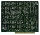
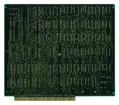
Reproducing the Lisa 2 Card Stack: The CPU Card

warmech

Tinkerer
Oct 30, 2021
79
101
33
On to unfortunately bigger things! Next up is the CPU card and, boy oh boy, is this going to suck. First and foremost, a huge thank you to user jamesdenton over at LisaList for providing me with a busted CPU card, as he's allowed me to depopulate it and scan it for reference for this task. I need to find someone/somewhere with a 1200dpi scanner that can manage this board, but it will be nice to have a high resolution image set to refer to.

The schematics have been replicated and I'll be starting in on the board layout once I have the scans in hand; all said and done, this was about a weeks worth of work in my free time so I'm happy it went as fast as it did. I got this done in about the same time it took me to do the RAM card's schematics, so I'm going to interpret that as having at least advanced my skills a little bit, lol. I'm not looking forward to laying down all the traces, as the number of them is substantially higher than the RAM card. It may be a couple of weeks before this is ready, but I'm looking forward to it being done.

Here's where I am at the moment - this should look better in a few days, lol...

Screen Shot 2022-08-08 at 1.24.21 AM.png
 

warmech

Tinkerer
Oct 30, 2021
79
101
33
Okay, small update... well, less an update and more just providing some reference images. They're a bit large, but they're a fraction the size of their TIFF parents. These are unfortunately only 400dpi; I have access to another large format scanner that can go up to 12800dpi (lol, each side of the CPU card would have taken ~8 hours to complete), but no matter what the scans kept coming out fuzzy. I'm looking for something that will do at least 600, but would prefer 1200 or greater. When this all goes to GitHub, better scans will be available there.
 

Attachments

  • cpu_front_280mmw_x_233mmh_(244mm_card_edge).jpg
    cpu_front_280mmw_x_233mmh_(244mm_card_edge).jpg
    3.7 MB · Views: 81
  • cpu_rear_280mmw_x_233mmh_(244mm_card_edge).jpg
    cpu_rear_280mmw_x_233mmh_(244mm_card_edge).jpg
    3.3 MB · Views: 81
  • Like
Reactions: Patrick

warmech

Tinkerer
Oct 30, 2021
79
101
33
Going to have to take a few days of after-hours progress off on this to rapidly install a drainage system for my yard before round two of heavy rain hits the DFW region this coming weekend. Spent yesterday morning digging a trench in my back yard to prevent my shop from flooding, so we're just going to fix that now, lol.

In the mean time, here's a quick progress pic to keep y'all posted. I'd say this is around 35-40% done at the moment:

Screen Shot 2022-08-23 at 10.29.33 AM.png


Also, what the heck is this, Apple?

Screen Shot 2022-08-23 at 10.35.17 AM.png


There are several right-angle traces on this thing, which I always thought was a big no-no due to EMI/cross-talk. Oh well; their engineers probably know better than myself, an untrained hobbyist with no formal education in any of this, lol.
 
  • Like
Reactions: Patrick

AndyDiags

Tinkerer
Dec 18, 2021
92
163
33
4 layer board! Good luck on this endeavor, I wish you no faults on your 1st revision.
Looking at that board scan, the "USA" part of "Made in USA" seems suspiciously covered up. Could it be that this board was designed in USA, but subsequently produced abroad, hence the cover-up?
 

warmech

Tinkerer
Oct 30, 2021
79
101
33
4 layer board! Good luck on this endeavor, I wish you no faults on your 1st revision.
Looking at that board scan, the "USA" part of "Made in USA" seems suspiciously covered up. Could it be that this board was designed in USA, but subsequently produced abroad, hence the cover-up?
Thanks - I'll take any luck I can get, lol. To answer your question: yes - you're spot on the money! The scan may not show it very well, but on the top-right of the rear of the PCB is a very faint (almost to the point being gone) silkscreen area which reads "MADE IN SINGAPORE".

Also, I've finally got 1200dpi scans of the CPU and RAM cards, so I'll find a place to get those posted sometime soon. The CPU TIFFs are 270MB and 300MB, so I'm going to need to find some place that can absorb something that large and not complain. They need to be trimmed down to remove the excess waste area in the scan, so they'll probably come out to 250MB each when they've been cleaned up.
 

warmech

Tinkerer
Oct 30, 2021
79
101
33
Well, almost two months later and here we are:

front.png


back.png


Not visible are the two inner layers form +5V and ground (well, DGND). This is effectively 100% complete, but I'm trying to get one last piece of cosmetic flair to work before calling it done. The software I'm working with (EasyEDA) does not make it easy to render the top and bottom substrates translucent by way of removing the masking/paste layers, so I'm trying to figure that out presently. As you can see with the front side, only the "1" is visible in the layer indicator, when it should look like this:

Screen Shot 2022-09-19 at 12.19.26 AM.png


Oh well, I'll get there eventually. Either way, my goal of finishing by the end of the weekend has been met, so I'm happy at the moment. In all, this card has over 1,800 traces that were reproduced by hand - no autorouting, just manually tracking each net by hand. Some license was taken when arranging the final traces but they are, in both count and connectivity, a 1:1 match to the original card; that is to say, this card is an electrically equivalent reproduction of the original PCB with a couple of minor updates. Which brings me to...

Updates! After speaking with AlexTheCat123 over at LisaList, I decided to keep this as close to the original hardware as possible save for a couple quality of life improvements:
  • Connections requiring factory bodge wires have been corrected; the original broken traces are absent from the card and their bodged corrections have been routed as proper traces.
  • The +5V jumper from the CPU section of the schematics has been made more apparent, with a J1 designation of the front of the card.
I didn't keep close track of my time but I'd estimate that there's between 80-100 hours in this thing by now, all of which I would say are worth it. This is a cool piece of Apple history that is now preserved at the informational level and, for that, I am very excited. For now, though, I'm going to set this thing aside for a couple of days and clear my head. Mid-week I'll come back with fresh eyes and take another very close look at everything to check for issues; just because there are no DRC errors doesn't mean it's ready to set sail.

If anyone has experience with EasyEDA and can point me in the right direction with respect to rendering a section of a top or bottom layer translucent, hit me up!

Will,
 

warmech

Tinkerer
Oct 30, 2021
79
101
33
Quick update for anyone following. Version 1.0 of the PCB is going to get a second set of eyes doing one last sweep and then it's off to fabrication. With the help of the person working on the I/O card, we (they, really) were able to figure out how the layer indicator transparency needed to work, so that's all settled out. If all turns out well and no further revisions are required, this might very well be a done deal by the end of next weekend! If so, expect a link here to GitHub with high-res scans of RAM and CPU cards; Gerber files; exports of the EasyEDA projects (if anyone wants to tool around with the designs); and documentation for the cards.

Screen Shot 2022-09-22 at 2.00.10 PM.png


Screen Shot 2022-09-22 at 2.00.34 PM.png
 

warmech

Tinkerer
Oct 30, 2021
79
101
33
Very minor update time!

Not long after this came in I got it populated and started testing. Ran into some issues initially and started diving into them, but ended up hitting some roadblocks due to a lack of time and tools, as well as a still in-progress understanding of Lisa hardware that just wasn't where it needed to be to probe much farther. Alex has been helping me understand the Lisa hardware more and more, though, so I'm picking up more knowledge as I go. He agreed to take a look, as things were getting stupid busy at work for me, so off it went to him for the moment. One of the things we immediately realized was a royal pain when it came to diagnosing Lisa hardware in-depth was the inability to have the card cage outside of the Lisa when testing. So, I whipped these up and am sending them of to have them fabbed:

Screen Shot 2022-11-24 at 2.26.42 AM.png


Screen Shot 2022-11-24 at 2.09.27 PM.png


As their names imply, these are extension harness PCBs that use IDE cables to extend the motherboard outside of the chassis and the CPU and I/O cards away from the motherboard for more extensive testing. I need to reduce the number of "perforations", but they are meant to just snap apart and wire up in order to reduce the number of fabbed boards and save on cost. These were a quick and dirty solution, but they should make diagnosing Lisa hardware issues a bit easier in the future.
 

DosFox

New Tinkerer
Dec 3, 2022
15
9
3
Impressive work! Have the current schematics/gerbers been uploaded to github yet?

I'm still a bit in awe that I started this exact same project, and I've only just found out I've been beaten to it!
 

warmech

Tinkerer
Oct 30, 2021
79
101
33
Impressive work! Have the current schematics/gerbers been uploaded to github yet?

I'm still a bit in awe that I started this exact same project, and I've only just found out I've been beaten to it!

Thanks! :)

Some have, some have not. Alex, the other person working on this, has uploaded his work so far. He's got some other Lisa stuff on his github as well that's absolutely worth checking out, like a repro of the SCSI card. If it's in one of his repos, it's been tested and verified as working. He's tackled the motherboard, the two port parallel card, and the I/O card and I've been working on the CPU and RAM cards. My work is still in-progress due to a boot issue with the CPU card that Alex is currently hunting down (hence the need for the extensions in some form or another). The RAM card is done and needs to be fabbed and tested as well. I'd prefer to have both at 100% before tossing gerbers out there, as I'd hate for someone to just have some made without reading the fine print and then be stuck with some very much not cheap and also not working four layer boards. Eh, I may go ahead and upload them anyway if you're interested in taking a look; probably best a copy of those things lives somewhere else anyway. The schematics need to be redrawn, as they are absolute garbage; however, even just six months out, I am a magnitude of order better at drawing them than I was when I started.

I've also got a SIMM-based RAM card reproduced (also needs to be fabbed and tested) and am testing a PSU replacement that lets you drop in an ATX PSU. I also have a couple other things in the pipeline that Alex and I are working on. I recently picked up another Lisa 2 that had a 20MB MFM hard disk in it whose controller card we're working on reproducing. I've dumped the ROM (attached below) off of it and Alex should have a blank PCB to work on shortly. It uses all off-the-shelf parts and, oddly, it has a serial header. No idea what that's for just yet (my working Lisa parts are with Alex at the moment and the one I picked up recently is in need of work), but the ROM has some pretty telling ASCII in it that we're pie-in-the-sky hoping is a low-level format utility accessible via serial. I still need to work on the Lisa Lite and video board, as well as put instructions together for the yoke adapter to convert the screen to Macintosh pixel width, but everything is still marching along.

Below is the SIMM card; I'd originally reproduced it based on scans but with the acquisition my second Lisa recently, it had one in it that I can now completely verify some questionable traces. So far it's 1:1, so it's probably in the clear.

Screen Shot 2022-12-02 at 11.03.22 PM.png


And here's the PSU replacement I've cobbled together. It uses a cheap buck-boost converter to produce the 33v that the video board needs, but otherwise is all driven by an ATX PSU that can output +/- 5 and 12 volts. If you have a dead 1.2A Lisa PSU, you can salvage the video control pots from it or use cheaper, smaller, and more easily obtained pots for the contrast and brightness controls.

Screen Shot 2022-12-02 at 11.08.02 PM.png


Strangely, that's exactly where I found myself a few months ago. I figured I'd start reproducing the hardware, only to stumble onto Alex's work and wind up where we are now. We both work out of EasyEDA, so if you have an account I'd be glad to share what I've done with you. It's... more and more pedestrian the farther back you go, so have mercy if you see something that looks like a doofus drew it. And heck, I'm going to go ahead and just fill out a repo with what I presently have; it needs to be out there anyway. I'll update you when I've got it populated.
 

Attachments

  • 341-8005_REV_C.bin
    16 KB · Views: 109
  • Like
Reactions: LeadedSolder

DosFox

New Tinkerer
Dec 3, 2022
15
9
3
Wow. Just... Wow! That is more or less exactly the same objectives I was planning to complete. You even cloned the SunRem 2mb RAM card!!

Even the idea of replacing the power supply with an ATX PSU - I guess great minds do think alike!

I suppose in a way that my end goal is marginally different in a way - I wanted to produce an entire Lisa from scratch as opposed to creating cards to replace damaged ones. My own research revealed that on a 2/5 there's only two "custom" parts - the main crystal oscillator and the COP microcontroller. However there are already proven workarounds to those issues.

Firstly, you can order custom oscillators - it's the way Sapient Tech got around that issue as you can clearly see a four pin oscillator as opposed to the two pin crystal Apple used, so that would just need a minor tweak on the CPU board to replace.

Additionally, the COP has already been reverse engineered (http://john.ccac.rwth-aachen.de:8000/patrick/COPSreader.htm). An adapter has also been made that uses the ROMless version of the COP, and has been verified as working in a Lisa.

I do have a full archive of almost all Lisa related ROMs as well - including the difficult to find SunRem 2/5 IO ROM that allows a 2/5 to use 800k Macintosh drives!

In the end my own goal is to produce a custom motherboard that contains the LITE adapter, keyboard interface (likely with an ADB to Lisa adapter onboard as well) with video coming from the seldom used composite video out at the rear. It will also be powered by an ATX PSU. As I'll be avoiding using the Lisa analog board, the PSU will only need to provide standard 5v/-5v/12v/-12v voltages.

The custom motherboard will allow yours and Sam's boards (as well as original Apple and Sapient boards) to be used to build a functional replica of a Lisa.

Further goals may involve tweaking your designs to avoid the difficult to find components - adding the custom four pin oscillator, replacing the 6504 with a 6502, and adding the ROMless COP in place of the COP421. I may also go further to reduce the complexity of the boards, and look into the feasibility of a single board Lisa.

Predominantly I've been using Altium/KiCAD for my own projects - but I wouldn't mind making an account so I can have a look at the other designs.

It's a shame that my day job of being an Electronics Engineer has gotten in the way of my hobby in Amateur Electronics!
 

warmech

Tinkerer
Oct 30, 2021
79
101
33
Wow. Just... Wow! That is more or less exactly the same objectives I was planning to complete. You even cloned the SunRem 2mb RAM card!!

Even the idea of replacing the power supply with an ATX PSU - I guess great minds do think alike!
Heh, thanks! I know the PSU replacement isn't the best, but I wanted to at least give it a try to get something working put together as a proof-of-concept. Both of mine are dead beyond repair and I've just been using an ATX PSU hacked into a cut-down JAMMA fingerboard. The soft power circuit is pretty low-tech (just a transistor serving as an intermediary between the ON/OFF line on the Lisa and the PS_ON line on the PSU) and could probably be improved. Power supplies are not my strong suit, so I stuck with "off-the-shelf" wherever possible. And the Sun RAM card was fun to figure out! The schematic looks like garbage but, now that I have a real one in hand and I'm not relying on JPEG-artifacted scans (there were a few connections that I just couldn't verify and had to make an educated guess about), I need to go back and check every trace and redraw them to look nicer. Once I get my cards back from Alex, that will be the first thing I order for testing. I've tried to order as few revisions to four layer stuff as possible due to cost because, oof, that stuff ain't cheap. :(

Additionally, the COP has already been reverse engineered (http://john.ccac.rwth-aachen.de:8000/patrick/COPSreader.htm). An adapter has also been made that uses the ROMless version of the COP, and has been verified as working in a Lisa.
After I came across that page a while back, I bought a ROMless COP402 juuuuuust in case. Thankfully, it's turned out to be unnecessary so far; I haven't tested the second COP I have, but that'll be an easy thing to determine in the near future once I have my first (now working) Lisa back. If I were at all capable of porting the COP400 assembly (or had a much better grasp on microcontrollers), I'd love to just replicate its functionality in something more modern (and plentifully available). Stepleton, over at 68KMLA/LisaList, mentioned this sentiment as well: "If there were eighteen of me, then the seventeenth would work on the COP421 replacement. It would extend the protocol by which it talks to the rest of the Lisa by including a new command and response for dates beyond 1995. It would probably also include a CR2032-backed RTC." I can always dream, lol.

I suppose in a way that my end goal is marginally different in a way - I wanted to produce an entire Lisa from scratch as opposed to creating cards to replace damaged ones. My own research revealed that on a 2/5 there's only two "custom" parts - the main crystal oscillator and the COP microcontroller. However there are already proven workarounds to those issues.

Firstly, you can order custom oscillators - it's the way Sapient Tech got around that issue as you can clearly see a four pin oscillator as opposed to the two pin crystal Apple used, so that would just need a minor tweak on the CPU board to replace.
Huh. I had no idea you could just... order a custom oscillator. That's extremely handy, as I was having a dog of a time trying to find a 20.whatever MHz crystal for the CPU card. I had a spare from the dead card that was generously donated so I could depopulate and scan it which, thankfully, wound up working. Outside of that, I had no idea how that would have otherwise been addressed.

I do have a full archive of almost all Lisa related ROMs as well - including the difficult to find SunRem 2/5 IO ROM that allows a 2/5 to use 800k Macintosh drives!
Sweet! It's amazing to me that there are still un-dumped ROMs for parts of the Lisa at this point. Alex is looking for a quick-boot ROM for the Sun SCSI card that apparently hasn't been dumped, and the firmware for the Sun MFM HD was un-dumped until, well, now I guess.

In the end my own goal is to produce a custom motherboard that contains the LITE adapter, keyboard interface (likely with an ADB to Lisa adapter onboard as well) with video coming from the seldom used composite video out at the rear. It will also be powered by an ATX PSU. As I'll be avoiding using the Lisa analog board, the PSU will only need to provide standard 5v/-5v/12v/-12v voltages.

The custom motherboard will allow yours and Sam's boards (as well as original Apple and Sapient boards) to be used to build a functional replica of a Lisa.

Further goals may involve tweaking your designs to avoid the difficult to find components - adding the custom four pin oscillator, replacing the 6504 with a 6502, and adding the ROMless COP in place of the COP421. I may also go further to reduce the complexity of the boards, and look into the feasibility of a single board Lisa.
This is kind of where I wanted to head one day as well - a single or double board Lisa with integral LisaLite, MFM HD controller and/or ProFile emulator, RAM (as SIMMs, maybe with an option to toggle the 4MB RAM mod if you wanted to go the MacWorks route), SCSI, and video signal converter for use with modern displays. Again, if my knowledge of MCUs was better, I'd love to just replace the COP421 outright with something newer and bake in ADB/OG Macintosh keyboard support if you really wanted as close a look as you could get to a Lisa keyboard without spending (checks eBay) $400-600 on one.

In the interim, once the core hardware is up and running, I'd love to figure out a way to get usable video out of a Lisa without going the general-purpose route with something like an OSSC or RGB2HDMI. The display is low enough in resolution that something like a Pico Pi could probably do the trick. My biggest fear with my Lisas so far isn't a card cage issue but a CRT one - if either of their flybacks or tubes takes a dirt nap, that may well be the end of things for that Lisa. The CRT is probably replaceable with something comparable out of another monochrome display, but the flybacks are what I lose sleep over. I've become soft in my years of working on W&G K7000 arcade displays, lol - their flybacks are still being reproduced, thankfully.

Also, I saw your efforts to find a suitable replacement for the 6504 on twitter - lol, I had no Idea those were all functionally the same! So you can just (with some adapting), sub anything in the 6502/4/7 family for any other 6502/4/7 on the I/O card and it just... works?

Lastly, stepleton brought up the thought that the IDE-based card extenders may introduce too much signal interference, so I whipped up a quick set of 90 degree risers to let you just flip the cards over and keep them as close to the motherboard as possible. They use the vertical alignment notches for stabilization, so they should be rather stable; I just need to design a quick and dirty set of 3D-printed standoffs to keep the cards level and they should be good to use. Oddly, there seems to be just enough of a gap between the I/O card notch and the back of the card cage that both the I/O and CPU cards fit just about perfectly; the CPU card has about a +/- 1mm shortfall, but should still set just fine into the edge connector. Makes me wonder if Apple had a similar setup for testing/diagnosis.

Screen Shot 2022-12-04 at 8.16.14 PM.png

Screen Shot 2022-12-04 at 8.16.35 PM.png
 
  • Like
Reactions: DosFox

DosFox

New Tinkerer
Dec 3, 2022
15
9
3
Heh I would worry too much about the schematics and designs being a mess - so long as they're functional it doesn't matter! You can always clean them up later.

The COP would be neat to reverse engineer, but I think there are enough ROMless version of the COP (and the soviet clones!) It's not a deal breaker for me, as the components are all still relatively easy to find. Stuff for the future I think!

The crystal was something I thought would be the end of the project. Thankfully talking to some friends (Chartreuse especially), they advised either to use an I2C clock generator or just order custom crystals! There's a small company that does vintage computer related stuff who charge £10 or so for a custom oscillator. I think when I checked by default they couldn't do the final 0.0005mhz (or so), but I you can definitely order custom ones - I mean sapient did it!

My ROM collection is basically what I could find scouring all of the corners of the internet. I'll have to double check as I think there's a lot of Sun Remarketing stuff as well someone dumped. The thing is I don't physically own a Lisa - hence this entire project. I'll need to check if the SCSI ROM is in there, it wouldn't surprise me if it was.

I would love to build a single board Lisa. I feel I would probably leave the COP as a ROMless COP with a baked in adapter, aside from that it'll just use the Lisa to ADB clone and pretty much all of your schematics 😂
Would be pretty sweet to just plug an ADB keyboard, an M0100 mouse and an external 400K floppy drive or floppy emu and it would all just *work*.
Also would be nice to have the option of using either a built in profile emulator (thanks Sam!) or an external real life profile. I'm still amazed all the work you and Sam have managed to complete.

I suppose I'm really interested in getting MacWorks and system 7 working on it - imagine the bragging rights! At that point you're able to get it running a TCP/IP stack so you can get it online with email, web browsing and BBSing. Not to forget about having the ability to run MacFlim.

In terms of video signal, I think the composite out that's already on the 2/5 will suffice. I've seen examples of it syncing nicely with modern ish TVs/monitors, so it should be ok for a project! If the worst comes to the worst I suppose it will probably easy to add support for TTL monitors and go from there with modern converters and adapters.
I've had a fair bit of experience with macintoshes and the gargantuan two page display - but I would prefer to avoid working with high voltage if I can!

Wait you've seen my twitter account? Oh no I'm being watched!
But yes, the 6504, 6507 share the same silicon as the 6502. I think the 12 or so unused pins are either just left disconnected or tied high or low internally. It does really look like if you replace the 6504 with a 6507 in an IO board it will working with literally no hardware changes! If you feel daring would you want to try that out?

Personally I feel that IDC cables will probably be fine for monitoring the bus, you're not going that far in terms of distances - so inteference wouldn't be a huge concern to me.

It really does seem that building brand new Lisa's is feasible - and with both of your amazing work it doesn't look like it's that far away from becoming a reality.

By the way you can message me on twitter if you want a slightly more direct way of talking!
 

LeadedSolder

New Tinkerer
Oct 27, 2021
35
7
8
Western Canada
www.leadedsolder.com
For custom clocks, there’s also Clock in a Can: https://github.com/schlae/ClockInACan

Edit: Unfortunately, I think the oscillator IC on it is not available anymore. Sigh. Maybe there’s a replacement or the fundamental design could be built into the board?

I am also starting on a project to do digital RGB (i.e. CGA) to VGA on the RPi Pico, I think it is very possible, and probably even feasible for weird Mac/Lisa mono video. It’s using the logic analyzer PIO example and the PicoVGA library. Waiting on the boards, maybe have it working early 2023? Firmware always takes me longer than hardware because it sucks.
 
Last edited: