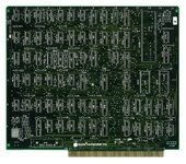
Wow. Just... Wow! That is more or less exactly the same objectives I was planning to complete. You even cloned the SunRem 2mb RAM card!!
Even the idea of replacing the power supply with an ATX PSU - I guess great minds do think alike!
Heh, thanks! I know the PSU replacement isn't the best, but I wanted to at least give it a try to get something working put together as a proof-of-concept. Both of mine are dead beyond repair and I've just been using an ATX PSU hacked into a cut-down JAMMA fingerboard. The soft power circuit is pretty low-tech (just a transistor serving as an intermediary between the ON/OFF line on the Lisa and the PS_ON line on the PSU) and could probably be improved. Power supplies are not my strong suit, so I stuck with "off-the-shelf" wherever possible. And the Sun RAM card was fun to figure out! The schematic looks like garbage but, now that I have a real one in hand and I'm not relying on JPEG-artifacted scans (there were a few connections that I just couldn't verify and had to make an educated guess about), I need to go back and check every trace and redraw them to look nicer. Once I get my cards back from Alex, that will be the first thing I order for testing. I've tried to order as few revisions to four layer stuff as possible due to cost because, oof, that stuff ain't cheap.

Additionally, the COP has already been reverse engineered (
http://john.ccac.rwth-aachen.de:8000/patrick/COPSreader.htm). An adapter has also been made that uses the ROMless version of the COP, and has been verified as working in a Lisa.
After I came across that page a while back, I bought a ROMless COP402 juuuuuust in case. Thankfully, it's turned out to be unnecessary so far; I haven't tested the second COP I have, but that'll be an easy thing to determine in the near future once I have my first (now working) Lisa back. If I were at all capable of porting the COP400 assembly (or had a much better grasp on microcontrollers), I'd love to just replicate its functionality in something more modern (and plentifully available). Stepleton, over at 68KMLA/LisaList, mentioned this sentiment as well: "If there were eighteen of me, then the seventeenth would work on the COP421 replacement. It would extend the protocol by which it talks to the rest of the Lisa by including a new command and response for dates beyond 1995. It would probably also include a CR2032-backed RTC." I can always dream, lol.
I suppose in a way that my end goal is marginally different in a way - I wanted to produce an entire Lisa from scratch as opposed to creating cards to replace damaged ones. My own research revealed that on a 2/5 there's only two "custom" parts - the main crystal oscillator and the COP microcontroller. However there are already proven workarounds to those issues.
Firstly, you can order custom oscillators - it's the way Sapient Tech got around that issue as you can clearly see a four pin oscillator as opposed to the two pin crystal Apple used, so that would just need a minor tweak on the CPU board to replace.
Huh. I had no idea you could just... order a custom oscillator. That's extremely handy, as I was having a dog of a time trying to find a 20.whatever MHz crystal for the CPU card. I had a spare from the dead card that was generously donated so I could depopulate and scan it which, thankfully, wound up working. Outside of that, I had no idea how that would have otherwise been addressed.
I do have a full archive of almost all Lisa related ROMs as well - including the difficult to find SunRem 2/5 IO ROM that allows a 2/5 to use 800k Macintosh drives!
Sweet! It's amazing to me that there are still un-dumped ROMs for parts of the Lisa at this point. Alex is looking for a quick-boot ROM for the Sun SCSI card that apparently hasn't been dumped, and the firmware for the Sun MFM HD was un-dumped until, well, now I guess.
In the end my own goal is to produce a custom motherboard that contains the LITE adapter, keyboard interface (likely with an ADB to Lisa adapter onboard as well) with video coming from the seldom used composite video out at the rear. It will also be powered by an ATX PSU. As I'll be avoiding using the Lisa analog board, the PSU will only need to provide standard 5v/-5v/12v/-12v voltages.
The custom motherboard will allow yours and Sam's boards (as well as original Apple and Sapient boards) to be used to build a functional replica of a Lisa.
Further goals may involve tweaking your designs to avoid the difficult to find components - adding the custom four pin oscillator, replacing the 6504 with a 6502, and adding the ROMless COP in place of the COP421. I may also go further to reduce the complexity of the boards, and look into the feasibility of a single board Lisa.
This is kind of where I wanted to head one day as well - a single or double board Lisa with integral LisaLite, MFM HD controller and/or ProFile emulator, RAM (as SIMMs, maybe with an option to toggle the 4MB RAM mod if you wanted to go the MacWorks route), SCSI, and video signal converter for use with modern displays. Again, if my knowledge of MCUs was better, I'd love to just replace the COP421 outright with something newer and bake in ADB/OG Macintosh keyboard support if you really wanted as close a look as you could get to a Lisa keyboard without spending (checks eBay) $400-600 on one.
In the interim, once the core hardware is up and running, I'd love to figure out a way to get usable video out of a Lisa without going the general-purpose route with something like an OSSC or RGB2HDMI. The display is low enough in resolution that something like a Pico Pi could probably do the trick. My biggest fear with my Lisas so far isn't a card cage issue but a CRT one - if either of their flybacks or tubes takes a dirt nap, that may well be the end of things for that Lisa. The CRT is probably replaceable with something comparable out of another monochrome display, but the flybacks are what I lose sleep over. I've become soft in my years of working on W&G K7000 arcade displays, lol - their flybacks are still being reproduced, thankfully.
Also, I saw your efforts to find a suitable replacement for the 6504 on twitter - lol, I had no Idea those were all functionally the same! So you can just (with some adapting), sub anything in the 6502/4/7 family for any other 6502/4/7 on the I/O card and it just... works?
Lastly, stepleton brought up the thought that the IDE-based card extenders may introduce too much signal interference, so I whipped up a quick set of 90 degree risers to let you just flip the cards over and keep them as close to the motherboard as possible. They use the vertical alignment notches for stabilization, so they should be rather stable; I just need to design a quick and dirty set of 3D-printed standoffs to keep the cards level and they should be good to use. Oddly, there seems to be just enough of a gap between the I/O card notch and the back of the card cage that both the I/O and CPU cards fit just about perfectly; the CPU card has about a +/- 1mm shortfall, but should still set just fine into the edge connector. Makes me wonder if Apple had a similar setup for testing/diagnosis.