"Spicy O'clock" project has started

Kay K.M.Mods

Active Tinkerer
Sep 23, 2021
286
631
93
Tokyo
www.kerosmm.com
Screen_Shot_2021-10-24_at_8.20.49_PM.pngspicyoclock1.png


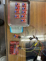
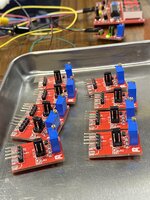
It's a bit early to announce this, but @Stephen has designed a beautiful PCB from my schematic, so I'll publish it here.
See my blog for the base. I improved and used this oscillator sold by a Japanese company called Akizuki Denshi, but I improved it to make it even easier to use.

What’s the Spicy O'clock!
o0651047914958389018.jpg
While working on several projects, I decided to make an adjustable clock oscillator that can be used mainly for the LC575 and LC475. Probably compatible with Wombat boards.
* Since the clock oscillator outputs at 1/2 of the actual clock, it actually works at half the indicated frequency.
The schematic is complete and you can set three mode settings by switching. In addition to the switch, there is a trimmer that can be adjusted in a variable trimmer. The maximum and minimum values in the mode are as follows.

Switching:

1: SL Mode 37.60MHz to 41.66MHz
2: LC Mode 41.66MHz to 46.50MHz
3: HT Mode 44.00MHz to 51.8MHz

SL Mode is a low level overclocking mode. It is used when the CPU is not tolerant or when overclocking is restricted due to the upper limit of the clock driver. The minimum is set to 37.6 because when combined with a 40Mhz CPU of 68040, 38MHz works without problems even without VRAM replacement.
LC Mode matches a standard Mac 040 / 40MHz CPU. This range is recommended because the LC575 (LC475 with a replaced clock driver) has a limit of about 42.7 to 42.8MHz.
HT Mode is specialized for machines that can support 43MHz or higher with some modification. Even in this case, it is difficult to raise it above 50MHz, so we set the limit to 51.8MHz.

how to use

The LC475 and LC575 methods are slightly different, but cut the pin input of the clock driver to interrupt this LC oscillator. The clock driver has a function other than generating the CPU clock, so it cannot be removed.
It is the speed of VRAM that is important for setting above 40MHz. Requires 70Ns or more of VRAM. (70Ns should support up to 43Mhz by any manufacturer) This 70Ns VRAM is also currently difficult to obtain and will be produced, but @JDW said the members here are going to make it with @Stephen 's PCB so I think it's a good idea to buy it!


Apr 26, 2022
Buy our Spicy O'Clock! here:

https://en.infinityproducts.co.jp/shop-1
スクリーンショット 2022-04-26 14.22.54.png

SMC-VRAM60Ns with higher clock support are also on the same page.
But this is not yet released.
If you want it immediately, please click the red button of "Notify when available".
We will notify you by email when it arrives.

スクリーンショット 2022-04-26 14.22.32.png
 
Last edited:

Kay K.M.Mods

Active Tinkerer
Sep 23, 2021
286
631
93
Tokyo
www.kerosmm.com
Just a prototype has been made. Make a change a little from here...There were two trace errors.
IMG_7166 2.jpeg


The prototype has a slide-switch, but we will replace the pin header and the jumper pin.


Test with LC475

Test with Centris650 (Wombat board)

The values in each mode are as follows. After all my calculations and actual values are slightly different😅

1: SL Mode 37.96MHz to 41.76MHz
2: LC Mode 41.79MHz to 46.48MHz
3: HT Mode 45.9MHz to 51.49MHz

I want to take overlap, but it will be a little wider than the lower range.
Test further...ahhhh😱
 
Last edited:
  • Like
Reactions: MacKilRoy and JDW

Kay K.M.Mods

Active Tinkerer
Sep 23, 2021
286
631
93
Tokyo
www.kerosmm.com
I've created an overlap to make it easier to use.

1: SL Mode 37.96MHz to 41.76MHz
2: LC Mode 41.79MHz to 46.48MHz
3: HT Mode 45.9MHz to 51.49MHz


In the actual product, the switch is abolished and replaced with a header pin and a jumper pin. This means less deterioration over time and less chance of failure.
スクリーンショット 2021-11-01 12.27.35.png
The variable resistance trimmer can be set to any frequency by simply setting the resistance measurement mode of the multimeter and measuring the number of ohms without using a frequency measuring instrument.

Variable resistance setting

Measure the DC resistance between V (+ 5V) and MS (Measurement Probe Point) with the Spicy O'Clock not energized. The calculation formula is as follows.
CPU clock = 20X (10 / ohm + 3.3)

CPU clock (MHz)  DC resistance between probes (Ohm)
35.6 2.3K
36.2 2.2K
37.0 2.1K
37.6 2.0K
38.4 1.9K
39.2 1.8K
40.0 1.7K
40.8 1.6K
41.6 1.5K
42.5 1.4K
43.4 1.3K
44.4 1.2K
45.4 1.1K
46.4 1.0K
47.6 0.9K
48.6 0.8K
50.0 0.7K
51.2 0.6K


Of course, the variable resistor can be adjusted steplessly, so the frequency can be changed in 1/100 MHz units.
 
Last edited:
  • Like
Reactions: MacKilRoy and JDW

Kay K.M.Mods

Active Tinkerer
Sep 23, 2021
286
631
93
Tokyo
www.kerosmm.com
We have updated some.The Ver1.2 PCB has already been ordered and will arrive at us in about a week.
Some will be distributed to testers and then the product will be released.
- The switch has been replaced with a pin header. It will not break down, so you can use it with confidence for decades.
- Added 4-pin headers in addition to the pads for each output. The user can choose which way to connect.
- Removed one unnecessary capacitor.

スクリーンショット 2021-11-12 10.08.50.png
 
  • Like
Reactions: Stephen

Kay K.M.Mods

Active Tinkerer
Sep 23, 2021
286
631
93
Tokyo
www.kerosmm.com
Hi folks, The Spicy O’Clock! V1.2a PCB modifications were perfect and I made 10 spicy oclocks yesterday, they works like a jet! We plan to sell 20 in the first batch. However, the production of the manual has not caught up. I'm writing a manual now, so please wait for a while.
 

Attachments

  • 9EFD13B6-A9B3-4010-A938-8786E837C2F0.jpeg
    9EFD13B6-A9B3-4010-A938-8786E837C2F0.jpeg
    2 MB · Views: 81
  • 1D4F3089-F697-4DBA-9FF6-99837A8A6BDB.jpeg
    1D4F3089-F697-4DBA-9FF6-99837A8A6BDB.jpeg
    1.3 MB · Views: 81
  • Like
Reactions: JDW and MacKilRoy

nottomhanks

Tinkerer
Oct 31, 2021
92
34
18
If I wanted to overclock my 575 board to 40 Mhz, do I need a 40Mhz CPU first? Or does the Spicy take care of that? Also, does the floppy drive and serial ports still work properly at that speed? I have some MIDI interfaces I'd like to hook up and use.
 

Drake

TinkerDifferent Board Vice-President 2023
Staff member
Sep 23, 2021
434
763
93
If I wanted to overclock my 575 board to 40 Mhz, do I need a 40Mhz CPU first? Or does the Spicy take care of that? Also, does the floppy drive and serial ports still work properly at that speed? I have some MIDI interfaces I'd like to hook up and use.
You still use the stock CPU on 575 board, due to the increased speed though serial timings are off and not usable. I am unsure of writing to floppy but my experience with overclocking older XT 8088/NEC V20 cpus is that writing to floppy is dependent on CPU (not sure if this is the case for Macintosh).
 

Kay K.M.Mods

Active Tinkerer
Sep 23, 2021
286
631
93
Tokyo
www.kerosmm.com
Spicy O’Clock! Calculator web version
スクリーンショット 2022-01-19 12.44.19.png

Spicy O’Clock! Can obtain the target frequency by measuring the resistance value of the probe point (between VIN <> MS).

I made an Excel macro with the formula I made above, but Stephen Arsenault made it a web version on his page and remade it. You can raise or lower it with the slider, so please try it.


This formula is a theoretical value. Please note that the values may vary depending on the usage conditions and individual differences. We also know that if your Mac has a high clock, the resistance will shift in the lower direction. A frequency counter is recommended if you want to set up for a high clock.
 

yock1960

Tinkerer
Mar 24, 2022
65
24
18
Hello new user here! I've been lurking on this forum for a few weeks now, after recently resurrecting a couple of vintage Macs that I used 20 or so years ago. After seeing the YouTube video by JDW on Spicy O'clock, I impulsively ordered one, without completely understanding all of the mods that would be required on my LC475, specifically the IC swap. I do see that there are MC88196DW80 available on eBay, but whether or not I could swap it out successfully is questionable at best. A question I have is, would leaving the MC88920 installed cause any damage or just make for a completely unsuccessful mod? As I watched JDW's video several times, I had already decided that ~42mhz would be my target and 40mhz would be better than the 33mhz I'm currently at, courtesy of a clip on gizmo purchased back in the day. This also as I do sometimes use a serial port joystick. I would assume that whatever course I may take, I would need to remove the clip on device...Correct?

Thanks!
 
  • Like
Reactions: Kai Robinson