Would work, with tape. I have a couple of options in hand already, one I think would fit, another I'm sure would, as the heatsink has a recessed area for the fan to sit in. Until I successfully get my machine running >33mhz, I won't really know how much a fan might be needed. At 33mhz, fanless is fine. I really would prefer to stay fanless, to keep this as quiet as possible.I was thinking about the fan thing this morning: what about this? https://www.amazon.ca/bluederst-Aluminum-Heatsink-Northbridge-Aluminium/dp/B087JMM659/ref=sr_1_32?adgrpid=1349101000615761&hvadid=84318967363132&hvbmt=be&hvdev=c&hvlocphy=5026&hvnetw=s&hvqmt=e&hvtargid=kwd-84318983113112:loc-32&hydadcr=620_1011851510&keywords=40mm+heatsink&qid=1648821583&sr=8-32
"Spicy O'clock" project has started
- Thread starter Kay K.M.Mods
- Start date
You are using an out of date browser. It may not display this or other websites correctly.
You should upgrade or use an alternative browser.
You should upgrade or use an alternative browser.
I find that the color classic fan is already pretty loud, so I wouldn’t care. Unless you have some crazy quiet CC fan replacement?
One more day (less actually) won't kill me, right?  My Spicy O'clock came today, but by the time I investigated the cause of my dog's 'high intensity' home defense mode, I missed
  the delivery person who needed a signature, if only I had known! Well, I scheduled for a pickup tomorrow...I try my best to keep my interaction with government employees to a minimum. Well, can't be helped! I didn't really expect it until next week, as it seemingly just got out if 'customs jail' yesterday. So, I should really be happy...if only...
My Spicy O'clock came today, but by the time I investigated the cause of my dog's 'high intensity' home defense mode, I missed the delivery person who needed a signature, if only I had known! Well, I scheduled for a pickup tomorrow...I try my best to keep my interaction with government employees to a minimum. Well, can't be helped! I didn't really expect it until next week, as it seemingly just got out if 'customs jail' yesterday. So, I should really be happy...if only...C$ 5.79 11%OFF | 4pcs 40x40x11mm Aluminum Heatsink Heat Sink Radiator Cooling cooler for Electronic Chip IC LED With Thermal Conductive TapI was thinking about the fan thing this morning: what about this? https://www.amazon.ca/bluederst-Aluminum-Heatsink-Northbridge-Aluminium/dp/B087JMM659/ref=sr_1_32?adgrpid=1349101000615761&hvadid=84318967363132&hvbmt=be&hvdev=c&hvlocphy=5026&hvnetw=s&hvqmt=e&hvtargid=kwd-84318983113112:loc-32&hydadcr=620_1011851510&keywords=40mm+heatsink&qid=1648821583&sr=8-32
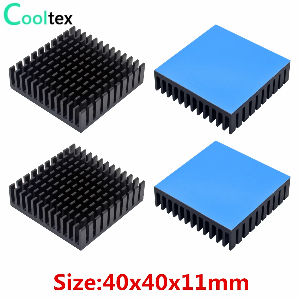
4.34US $ 13% OFF|4pcs 40x40x11mm Aluminum Heatsink Heat Sink Radiator Cooling Cooler For Electronic Chip Ic Led With Thermal Conductive Tap - Fans & Cooling - AliExpress
Smarter Shopping, Better Living! Aliexpress.com
I've been using these on my 040 machines as they easily accept a fan. The thermal tape does a good job too, at the point I'd say using paste vs tape is really just preference.
Thanks!I don't know...personally, I would find what a 'transplanted' American living in Japan, eats for breakfast interesting, but that's me.
I would also vote to keep content versus removing...there is the FF button, especially if you use 'chapters'.
")
Keep in mind that is 40mm. The heatsink I will show in my forthcoming video is 45mm and covers the entire top surface area of the chip. I think it's best to cover most of the chip where possible to maximize cooling.I was thinking about the fan thing this morning: what about this? https://www.amazon.ca/bluederst-Aluminum-Heatsink-Northbridge-Aluminium/dp/B087JMM659/ref=sr_1_32?adgrpid=1349101000615761&hvadid=84318967363132&hvbmt=be&hvdev=c&hvlocphy=5026&hvnetw=s&hvqmt=e&hvtargid=kwd-84318983113112:loc-32&hydadcr=620_1011851510&keywords=40mm+heatsink&qid=1648821583&sr=8-32
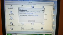
If you have an oscilloscope (oughta be 300 MHz or more) you can try verifying some of the basic specs of the MC88916, particularly the PCLK and BCLK frequencies, duty cycles, phase alignment, etc. If those look good the that the limiting factor must be the CPU or chipset, not the clock generator. The signals should be at the desired frequency and aligned in phase within +/- 9 nanoseconds (IIRC). Duty cycle is apparently critical too on the '040. 46%-54% of the clock period should be high/low. But I would wager that the clock generator is probably working well enough.Because the MC88916DW80 was mentioned by Kay, I should remind everyone that on my LC575 board, I have the slower MC88916DW55 chip. You can see that chip in this section of my Part I video. But despite that slower DW55 chip, I have broken the 50MHz barrier with Kay's new 2-chip VRAM. There's something so awesome about that, I really can't explain it in words. I am extremely grateful to the brilliant people who made this possible. It's incredible.
Next...
Only very rarely do I get Bus errors at 50.1MHz (in System 7.1), but I get them frequently at 50.5MHz and higher. What I do NOT know is if the Bus errors at 50.5MHz and higher are related to my having the slower DW55 chip. We need a larger pool of Mystic owners overclocking beyond 50MHz to know for sure, since I don't have time to swap my DW55 for a faster DW80 and test right now.
Lastly...
My Spicy Part II video is now in final editing and hopefully can be uploaded this weekend. Even after a lot of editing, it has still turned out to be 1 hour 10 minutes long. That's why I'm deciding if I want to cut out some of my game testing (which nicely demonstrates performance at a given clock speed) or just leave it all in (with my commentary, of course). Some people hate long videos, but I really do try to stay on point and provide useful information throughout the video. I don't talk about off-topic things like what I had for breakfast.
I will give Kay and Paypal supporters a preview of my new Spicy Part II video before it goes public, hopefully this weekend. If someone finds a problem, then I may need to edit and export again for a lovely 6.5 hours, and then re-upload. That "bug fix" process often delays the official release of my videos.I need a faster modern Mac! Don't we all? But when it comes to a faster Color Classic Mystic, Spicy O'Clock and that new low latency VRAM certainly delivers!
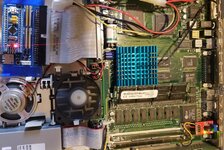
Boy, this is fiddly! Tiny components (R93!), tight spaces (connecting Vcc and ground on the logic board component), fragile case plastic (broke a tab, removing the logic board), broke it again re-seating the logic board, broke the other fan clip re-installing the fan...good thing I bought a decent sized bottle of acetone! Somebody needs to make a new pizza box case!
But, stage 1 has been successfully (so far) completed...let the benchmarking/stability testing begin! I moved the jumper to SL, turned and turned and turned the adjustment, finally stopping at about 2.176k ohms for ~37mhz. As I have not received the MC88196DW80 yet...and am still nervous about swapping it...I will stay here for a while, checking things out. So far, all I've found is that restarts hang, cold boot works fine however.
I'm thrilled that doing this mod has given me back the option of 800x600. This was some 832x??? or something weird like that...that was italicized and my LCD monitor didn't support it! I'm also thrilled with the free floppy drive gear! Thanks Kay!!
Going back to the adjustment screw, does it stop turning at some point....should I be cautious when getting close to the upper or lower range? I'm unfamiliar with these.
Attachments
I have access to 2 scopes at the office, both 100MHz only. I also have a logic analyzer, but it too maxes out at 100MHz, and only for 2 channels.If you have an oscilloscope (oughta be 300 MHz or more) ...
@Zane Kaminski You do a lot of design and testing work. What reasonably priced 500MHz scope would you recommend for general use? Being able to read logic signals too might be a plus. (I'm looking beyond this one application, mind you.)
It will keep turning when you reach the upper and lower limit, but if you listen carefully it should click a little bit when you reach the limits, and then keep clicking faintly when you make another full turn in that same direction, showing you that further turning will not result in additional resistance changes. If you have a meter attached such that you can see resistance of the blue POT on Spicy, that will clearly show you when you reach the upper or lower limits, because further turns in that same direction will not result in increased/decreased resistance changes.Going back to the adjustment screw, does it stop turning at some point....
Last edited:
When my car wouldn't start this morning, I accelerated my testing schedule, while I wait for the battery to charge.
I decided to see where the ceiling was on my LC475 with the MC88920 still installed. I started at around 1.72K ohms. Running OS 8.1, it got past RAM check and started to boot, but hung with the progress bar perhaps 1/10 of the way across....before any icons appear at the bottom of the screen. From there I backed the pot 1/2 turn and tried again. This repeated with exactly the same results until finally booting @ 39.37mhz. Just like Kay said!
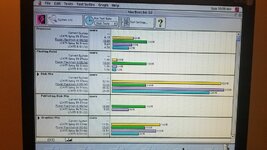
I then proceeded to run some benchmarks and Apple Personal Diagnostics. Diagnostics passed, interestingly, at 36.51mhz, the RAM test would end at about 60% with a 'test stopped by user'....huh, I didn't stop it, but it completes at 39.37mhz.
Something else I find interesting, that stands out with the MacBench 3.0 results, are the Disk Mix result and the Graphics Mix. For the Disk Mix, the results decreased from 39.37Mhz versus 36.51Mhz. I use a BlueSCSI 1.1a for drives. It's slower than a physical drive in some ways, but much quieter and I have way more storage. This result however makes me wonder if there is some sweet spot for performance that is something < 39.37mhz and > 33mhz.
Which brings me to the Graphics Mix scores. The blue bar @ 8.23 was from just prior to performing the Spicy install and was nominally 33mhz. But when I ran MacBench at 36.51mhz, the increase was out of proportion to the other scores. The 33mhz overclock method that was used was a small clip on device that fit over an IC just behind the video port. These results make me think that this device did not speed up some part of the video system. I know I was surprised/pleased at the game testing that I did yesterday with only a 'nominal' 3.5mhz increase.
So now I'm left wondering if it's worth the risk of me bodging up the logic board by swapping the MC88920 when the MC88916DW80 arrives if the BluSCSI is a limiting factor. I'd appreciate any thoughts on this!
I decided to see where the ceiling was on my LC475 with the MC88920 still installed. I started at around 1.72K ohms. Running OS 8.1, it got past RAM check and started to boot, but hung with the progress bar perhaps 1/10 of the way across....before any icons appear at the bottom of the screen. From there I backed the pot 1/2 turn and tried again. This repeated with exactly the same results until finally booting @ 39.37mhz. Just like Kay said!
I then proceeded to run some benchmarks and Apple Personal Diagnostics. Diagnostics passed, interestingly, at 36.51mhz, the RAM test would end at about 60% with a 'test stopped by user'....huh, I didn't stop it, but it completes at 39.37mhz.
Something else I find interesting, that stands out with the MacBench 3.0 results, are the Disk Mix result and the Graphics Mix. For the Disk Mix, the results decreased from 39.37Mhz versus 36.51Mhz. I use a BlueSCSI 1.1a for drives. It's slower than a physical drive in some ways, but much quieter and I have way more storage. This result however makes me wonder if there is some sweet spot for performance that is something < 39.37mhz and > 33mhz.
Which brings me to the Graphics Mix scores. The blue bar @ 8.23 was from just prior to performing the Spicy install and was nominally 33mhz. But when I ran MacBench at 36.51mhz, the increase was out of proportion to the other scores. The 33mhz overclock method that was used was a small clip on device that fit over an IC just behind the video port. These results make me think that this device did not speed up some part of the video system. I know I was surprised/pleased at the game testing that I did yesterday with only a 'nominal' 3.5mhz increase.
So now I'm left wondering if it's worth the risk of me bodging up the logic board by swapping the MC88920 when the MC88916DW80 arrives if the BluSCSI is a limiting factor. I'd appreciate any thoughts on this!
Attachments
I can only say that those test results don't follow what I've been seeing in my 4 months of testing on the LC575 motherboard, so we really, really need another LC475 user who also has Spicy O'Clock to explain in detail what happens on their machine, at the same clock frequencies you used, and while using those same benchmark apps.When my car wouldn't start this morning, I accelerated my testing schedule, while I wait for the battery to charge.
I decided to see where the ceiling was on my LC475 with the MC88920 still installed. I started at around 1.72K ohms. Running OS 8.1, it got past RAM check and started to boot, but hung with the progress bar perhaps 1/10 of the way across....before any icons appear at the bottom of the screen. From there I backed the pot 1/2 turn and tried again. This repeated with exactly the same results until finally booting @ 39.37mhz. Just like Kay said!
I then proceeded to run some benchmarks and Apple Personal Diagnostics. Diagnostics passed, interestingly, at 36.51mhz, the RAM test would end at about 60% with a 'test stopped by user'....huh, I didn't stop it, but it completes at 39.37mhz.
Something else I find interesting, that stands out with the MacBench 3.0 results, are the Disk Mix result and the Graphics Mix. For the Disk Mix, the results decreased from 39.37Mhz versus 36.51Mhz. I use a BlueSCSI 1.1a for drives. It's slower than a physical drive in some ways, but much quieter and I have way more storage. This result however makes me wonder if there is some sweet spot for performance that is something < 39.37mhz and > 33mhz.
Which brings me to the Graphics Mix scores. The blue bar @ 8.23 was from just prior to performing the Spicy install and was nominally 33mhz. But when I ran MacBench at 36.51mhz, the increase was out of proportion to the other scores. The 33mhz overclock method that was used was a small clip on device that fit over an IC just behind the video port. These results make me think that this device did not speed up some part of the video system. I know I was surprised/pleased at the game testing that I did yesterday with only a 'nominal' 3.5mhz increase.
So now I'm left wondering if it's worth the risk of me bodging up the logic board by swapping the MC88920 when the MC88916DW80 arrives if the BluSCSI is a limiting factor. I'd appreciate any thoughts on this!
I spent a HUGE amount of time testing, changing the clock speed, testing, and repeating that. Four months of testing in all, testing something nearly every day. So while I have become the world's expert (outside Kay) on the LC575 board, I really have no idea what happens on other boards, especially those which haven't been recapped with OS-CON capacitors. In fact, I don't know what the benefits of OS-CON are on boards other than the 575 because I don't have first-hand experience with those other boards. I can only say that Kay and Drake and myself were unable to overclock to high speeds on the 575 board until we used OS-CON. Solid Tantalum caps won't cut it. OS-CON caps have significantly lower ESR.
Of course, the MC88920 on your LC475 board is another limiting factor, so until that is swapped out, the testing you're doing now may not accurate reflect what's possible. But as I said earlier, we really need more LC475 users to chime in to get a clearer picture on what's possible with your Mac.
I can only say that those test results don't follow what I've been seeing in my 4 months of testing on the LC575 motherboard, so we really, really need another LC475 user who also has Spicy O'Clock to explain in detail what happens on their machine, at the same clock frequencies you used, and while using those same benchmark apps.
I spent a HUGE amount of time testing, changing the clock speed, testing, and repeating that. Four months of testing in all, testing something nearly every day. So while I have become the world's expert (outside Kay) on the LC575 board, I really have no idea what happens on other boards, especially those which haven't been recapped with OS-CON capacitors. In fact, I don't know what the benefits of OS-CON are on boards other than the 575 because I don't have first-hand experience with those other boards. I can only say that Kay and Drake and myself were unable to overclock to high speeds on the 575 board until we used OS-CON. Solid Tantalum caps won't cut it. OS-CON caps have significantly lower ESR.
Of course, the MC88920 on your LC475 board is another limiting factor, so until that is swapped out, the testing you're doing now may not accurate reflect what's possible. But as I said earlier, we really need more LC475 users to chime in to get a clearer picture on what's possible with your Mac.
Yes, more results from more machines would be great. There are so many variables, I'm not sure any individual, certainly not myself, could really determine the root causes of any specific result.
I would really like to see results that use BlueSCSI, since this result was unexpected. Perhaps I will back the overclock down a bit and run it again, just to see. If it was only a percentage point or so, I would say test granularity, but 9 percentage points?
I'm almost tempted to pull the SCSI2SD out of my Mac Plus and try it, but it's much less easy to work with, additionally, the BlueSCSI is not compatible with the Plus.
For my case, another factor is that the machine needs recapping. I think I can accomplish that, but never having done it...and being a top class procrastinator...a bad combination...

After successfully accomplishing that, I will have two less excuses for not swapping the MC88920 and pushing the overclock up a bit more. If I succeed in that, I will consider purchasing faster VRAM, although it's unlikely that I would go the OS-CON route, so perhaps that would be pointless.
I would suggest you halt everything until you've recapped, and my advice is to use OS-CON or similar solid polymer capacitors with super low ESR to make 100% sure the craziness you are seeing is in no way whatsoever related to voltage instability on the motherboard, which likely is the case if you need to recap....another factor is that the machine needs recapping.
I'm still wondering if MLCC will perform just as good or better than the OS-CON for overclocking since they are the lowest ESR out of all of them. I guess I'll find out at some point when I decide to try overclocking at some point.
Ceramic caps are unfortunately a BAD idea for reasons I will now explain.I'm still wondering if MLCC will perform just as good or better than the OS-CON for overclocking since they are the lowest ESR out of all of them. I guess I'll find out at some point when I decide to try overclocking at some point.
Unless you use tiny capacitance values in the pF or nF range, such that you can actually use NP0/C0G types, you would need to use an MLCC like an X7R. NP0/C0G caps don't have a voltage derating, which is great. But X7R and lesser caps lose a huge amount of rated capacitance as you increase the voltage across them. You might lose as much as 80% of the capacitance, unless you wildly overspec the voltage rating. That is why we call it "voltage derating."
For example, you'd need to use no less than a 50V MLCC X7R on a 12V rail, with a 100V spec MLCC being even better, in order to ensure that the rated capacitance of your MLCC is what you actually get when using it with that 12V rail. If you use a 25V MLCC X7R on a 12V rail, depending on the cap, your capacitance could drop by 50% or more. That is the biggest failing of going the MLCC route.
But there's more...
Ceramic caps are, well, ceramic. That means they can and do crack if there are a lot of jolts to to a circuit board. And the larger the cap is physically, the easier that can happen. The higher the voltage spec, the larger the MLCC will be.
Another issue is that ceramic caps make noise when they are hit with a pulsing waveform. You've probably heard some cheap power supplies do that. It's like a 1kHz buzzing sound. That's because MLCC caps physically increase and decrease in size with applied voltage! I kid you not. And when they do that, the PCB they are soldered onto acts as a speaker cone, amplifying the sound! Some ways to mitigate that include drilling holes in the circuit board around the caps (practical only on boards you design yourself), or using very expensive version MLCCs which have flexible ends.
But wait! That's not all!
Remember when I said you need a high voltage spec for X7R caps to be usable at their rated capacitance? Well, you won't be able to get large capacitance sizes in ceramics. For example: 100µF at 100V. But let's say you could get a 100µF 100V capacitor, and at a reasonable price. The size of the thing would be too huge to fit the existing circuit board pads!
I fully understand the logic behind using MLCCs. They have their place in design. I'd love to use 8mΩ MLCC's over a 25mΩ solid polymer OS-CON! But for reasons I just stated, it isn't a practical option, unfortunately. And again, if you go with a low voltage rated MLCC, you won't get but a fraction of the rated capacitance, and if the capacitance is too low, it's almost as if there was no capacitor there at all.
Like you I've had my concerns over the use of MLCC due to DC bias, but in reality I've been using them in old computers they will work fine regardless of DC bias.Ceramic caps are unfortunately a BAD idea for reasons I will now explain.
Unless you use tiny capacitance values in the pF or nF range, such that you can actually use NP0/C0G types, you would need to use an MLCC like an X7R. NP0/C0G caps don't have a voltage derating, which is great. But X7R and lesser caps lose a huge amount of rated capacitance as you increase the voltage across them. You might lose as much as 80% of the capacitance, unless you wildly overspec the voltage rating. That is why we call it "voltage derating."
For example, you'd need to use no less than a 50V MLCC X7R on a 12V rail, with a 100V spec MLCC being even better, in order to ensure that the rated capacitance of your MLCC is what you actually get when using it with that 12V rail. If you use a 25V MLCC X7R on a 12V rail, depending on the cap, your capacitance could drop by 50% or more. That is the biggest failing of going the MLCC route.
But there's more...
Ceramic caps are, well, ceramic. That means they can and do crack if there are a lot of jolts to to a circuit board. And the larger the cap is physically, the easier that can happen. The higher the voltage spec, the larger the MLCC will be.
Another issue is that ceramic caps make noise when they are hit with a pulsing waveform. You've probably heard some cheap power supplies do that. It's like a 1kHz buzzing sound. That's because MLCC caps physically increase and decrease in size with applied voltage! I kid you not. And when they do that, the PCB they are soldered onto acts as a speaker cone, amplifying the sound! Some ways to mitigate that include drilling holes in the circuit board around the caps (practical only on boards you design yourself), or using very expensive version MLCCs which have flexible ends.
But wait! That's not all!
Remember when I said you need a high voltage spec for X7R caps to be usable at their rated capacitance? Well, you won't be able to get large capacitance sizes in ceramics. For example: 100µF at 100V. But let's say you could get a 100µF 100V capacitor, and at a reasonable price. The size of the thing would be too huge to fit the existing circuit board pads!
I fully understand the logic behind using MLCCs. They have their place in design. I'd love to use 8mΩ MLCC's over a 25mΩ solid polymer OS-CON! But for reasons I just stated, it isn't a practical option, unfortunately. And again, if you go with a low voltage rated MLCC, you won't get but a fraction of the rated capacitance, and if the capacitance is too low, it's almost as if there was no capacitor there at all.
TDK actually has a very good guide for replacing electrolytic capacitors with MLCC explaining what you mentioned and appropriate use cases:
https://product.tdk.com/en/techlibrary/solutionguide/mlcc_replace-guide.html
https://product.tdk.com/en/system/files/dam/doc/content/sog/mlcc03_item06_en.pdf
For decoupling and smoothing which is generally what the caps being replaced on the Mac motherboards generally are, according to the guide the capacity can be reduced.
The fact is that voltage rating plays a lot smaller role than MLCC size when it comes to DC bias. Here's couple of pages that talk about it:
https://www.maximintegrated.com/en/design/technical-documents/tutorials/5/5527.html
https://community.infineon.com/t5/Knowledge-Base-Articles/DC-Bias-Characteristic-of-Multilayer-Ceramic-Capacitor-MLCC/ta-p/250035 You can verify this yourself by looking at the DC bias characteristics provided by different MLCC vendors:
Here's a link for anyone looking for DC-bias characteristics for different MLCC manufacturers. You will not see this info on Mouser or Digikey. Even for the same size, voltage, capacity and temperating rating the DC bias characteristics vary manufactuerer so it's worth while to take a look at the characteristics of the caps your looking at:
http://weblib.samsungsem.com/mlcc/mlcc-ec.do
https://product.tdk.com/en/search/l...ncsearch=1&_l=20&_p=1&_c=part_no-part_no&_d=0
https://www.murata.com/en-us/search/productsearch?partno=GRM32ER61C476KE15
https://spicat.kyocera-avx.com/product/mlcc/chartview/12065L105KAT2A
https://ds.yuden.co.jp/TYCOMPAS/ap/specificationSearcher?cid=C&u=M&Seri=HVC&SR2=LM,MP
Here's a comparison of the TDK XR5 100uf 2220 10V that I use vs the 6.3V:
Regarding cracking of large caps I've never had that happen on any of the computers I've use 2220 MLCCs on. Even after dropping boards they all survived. Maybe in an application that provided constant stress to the boards I would be more worried, but in a controlled environment like a house this is really a non issue in my opinion.
One of the interesting thing about MLCC vs other capacitors is that heat from soldering doesn't actually damage the caps. In fact heating caps past 125C does de-aging of the capacitor:
Electronic Component Distributor | Quest Components
Electronic components distributor with large in stock inventory. Over 130 manufacturers with electronic components added daily. In stock items ship same day.
 www.questcomp.com

Multilayer Ceramic Capacitors (MLCCs)
This article provides a discussion of multilayer ceramic capacitor (MLCC) basics, proper testing procedures, and what the aging/de-aging process is.
www.digikey.ca
Anyhow, bottom line is I've use ceramic caps in my LC 550 and LC630/580 with no such high pitch noise coming from the computers either and they work 100%. If you do get oscillating then just use other caps like al polymer or tantalums.
I don't care what people use in the end, but at the same time I don't think it's 100% right to say that they can't be used at all in replacing electrolytic caps in old equipment. Is it more of a hassle and take more reading to get the exact characteristics for the MLCCs. Yes. Do the cost more than most other replacement. Yes, especially at the higher capacities. But they will never leak, can be de-aged and have the lowest esr out of all caps. They are quite expensive so I usually reserve them for valuable computers and those I care the most for.
If anyone is curious I use size 2220 for 47uf and 100uf and for the smaller capacities I use 1210 size. I tried to get X7R or X5R in that order.
BTW I found some really awesome cheap 100uf 16v poly caps with very high life rating made by United Chemi-Con:
APXT160ARA101ME61G
https://www.mouser.ca/ProductDetail/661-APXT160A101ME61G
Hope this coherent. Girl friend about to kick me out for not sleeping lol
Attachments
Indeed, and I never said MLCC's "can't be used at all."... I don't think it's 100% right to say that they can't be used at all in replacing electrolytic caps in old equipment.
As to the other technical information you kindly researched and linked for us, I appreciate that very much and think it is good reading for those who are less informed about the caps we are talking about.
At this point, I would recommend that you acquire a Spicy O'Clock and then test how far you can overclock your LC580 board (which is basically the same as my LC575 board) with a known-good 040 CPU with onboard FPU (a 40MHz rated CPU being best) in combination with your MLCC capacitors.
I still feel that it is not prudent for me to preach general use of MLCCs in recapping, for the reasons given in my previous post. My arguments are not mine alone and this Panasonic White Paper parallels what I said. I should add that many decoupling applications have an aluminum electrolytic in parallel with a 0.1µF ceramic, and when swapping out the electrolytic with another ceramic, it opens the door to the anti-resonance phenomenon mentioned in the blue section of this TDK web page. MLCCs really do have serious caveats that require caution and a firm understanding of the theory and one's circuit board.
As to "less capacitance still being good enough," well, there's a lot of speculation in that, since none of us here designed the boards we are recapping, nor have I ever found a complete schematic of the LC575 or similar motherboards in order to do a more deep dive into circuit analysis.
As far as this particular discussion thread is concerned, I am focused on overclocking more than general use recapping. So what works for general recapping won't necessarily work for super high overclocks. The best rule of thumb is to shoot for the same capacitance "capacity" wherever possible. In other words, if you are swapping out a 47µF cap, a 22µF might still work and you may not notice a difference under normal use (and I know what TDK has to say on the matter), but it's difficult to argue that it really is OK until tested at your highest target overclock speed. Indeed, when clocking to high speeds, having a lot of capacitance with very low ESR really is a big deal. Drake and Kay and myself could not overclock as high until lower ESR caps were used, and those caps were OS-CON so we don't have DC Bias issues -- in other words, our 47µF OS-CON is 47µF, not 22µF or thereabouts.
So again, there is much testing that needs to be done to confirm the speculations -- even good speculations based on a firm understanding of the theory in combination with experience recapping with MLCCs. We aren't just recapping here. We are overclocking to extreme speeds. That's why I'm eager to hear your own Spicy O'Clock testing experiences with your MLCC recapped LC580 board and a good 040 CPU that can be overclocked to high speeds (i.e., beyond 50MHz).
Now, would even lower ESR caps like MLCC eliminate the Bus errors that I am seeing at 50.5MHz and higher? I cannot say until MLCCs are tried, but right now I lack the time to do that. Hopefully my forthcoming Spicy Part II video (which will be released within 24 hours) will encourage more people to test and sharing their own findings.
You are correct, you never said that they can't be used at all. You just mentioned that they "Ceramic caps are unfortunately a BAD idea". I interpreted it the wrong way.
Exactly. There's is a lot more thought that has to go into selecting and using MLCCs vs tants, poly tants and al poly.
Yup it using MLCC can create the awesome high pitch noise from the anti-resonance phenomenon. So far though I've had no problems on the LC 520, LC 580/630, Game Gear, Turbo Express, Mac 800K floppy drives amongst others.
The only place I've had high pitch noise happen after replacing the caps with MLCCs is the Macintosh Portable M5120 but I'm not 100% sure if it's the MLCCs to blame or not. I didn't dare try to turn it on before recapping and maybe it was already existing.
Yup exactly the point of this was to just say that I have boards LC580/630 boards that have been clocked to 40Mhz, had the CPU swapped to a full XC68040 rated at 40Mhz and had all the caps aluminum electrolytic caps replaced with MLCCs and it's working fine. It would be interesting to see how much it can be pushed with the Spicy O'Clock just to get an idea of how well the MLCCs work for overclocking. The MLCCs give a bit lower ESR than the al poly but not a huge leap like from the original caps or tants. Maybe the other characteristics of the MLCCs will be detrimental for overclocking.
One issue that will arise when comparing overclock results will be varying die quality of the CPU. Also there's the die revisions/shrinks to consider. I got an XC68040RC40 which will run hotter than an smaller die MC68040RC40 and maybe able to reach lower overclock regardless of the caps. To compare apples with apples for the caps I would have to have several matching boards and then test with the same CPU to remove die quality from equation.
I'm fortunate enough to actually have 4 x LC580/630 boards and 3x L575 boards I could play around with. Not sure I want to spends all the time doing that though right now. Personally I'm more interested in doing more hardware design. Still got a 68040 heatsink clip I want to finish designing before I do any overclocking. I just don't trust thermal tape since I've had it fail before in the past and don't like the idea of a chunk of metal floating around in the computer.
I still feel that it is not prudent for me to preach general use of MLCCs in recapping, for the reasons given in my previous post. My arguments are not mine alone and this Panasonic White Paper parallels what I said.
Exactly. There's is a lot more thought that has to go into selecting and using MLCCs vs tants, poly tants and al poly.
I should add that many decoupling applications have an aluminum electrolytic in parallel with a 0.1µF ceramic, and when swapping out the electrolytic with another ceramic, it opens the door to the anti-resonance phenomenon mentioned in the blue section of this TDK web page. MLCCs really do have serious caveats that require caution and a firm understanding of the theory and one's circuit board.
Yup it using MLCC can create the awesome high pitch noise from the anti-resonance phenomenon. So far though I've had no problems on the LC 520, LC 580/630, Game Gear, Turbo Express, Mac 800K floppy drives amongst others.
The only place I've had high pitch noise happen after replacing the caps with MLCCs is the Macintosh Portable M5120 but I'm not 100% sure if it's the MLCCs to blame or not. I didn't dare try to turn it on before recapping and maybe it was already existing.
As far as this particular discussion thread is concerned, I am focused on overclocking more than general use recapping. So what works for general recapping won't necessarily work for super high overclocks. The best rule of thumb is to shoot for the same capacitance "capacity" wherever possible. In other words, if you are swapping out a 47µF cap, a 22µF might still work and you may not notice a difference under normal use (and I know what TDK has to say on the matter), but it's difficult to argue that it really is OK until tested at your highest target overclock speed. Indeed, when clocking to high speeds, having a lot of capacitance with very low ESR really is a big deal. Drake and Kay and myself could not overclock as high until lower ESR caps were used, and those caps were OS-CON so we don't have DC Bias issues -- in other words, our 47µF OS-CON is 47µF, not 22µF or thereabouts.
So again, there is much testing that needs to be done to confirm the speculations -- even good speculations based on a firm understanding of the theory in combination with experience recapping with MLCCs. We aren't just recapping here. We are overclocking to extreme speeds. That's why I'm eager to hear your own Spicy O'Clock testing experiences with your MLCC recapped LC580 board and a good 040 CPU that can be overclocked to high speeds (i.e., beyond 50MHz).
Now, would even lower ESR caps like MLCC eliminate the Bus errors that I am seeing at 50.5MHz and higher? I cannot say until MLCCs are tried, but right now I lack the time to do that. Hopefully my forthcoming Spicy Part II video (which will be released within 24 hours) will encourage more people to test and sharing their own findings.
Yup exactly the point of this was to just say that I have boards LC580/630 boards that have been clocked to 40Mhz, had the CPU swapped to a full XC68040 rated at 40Mhz and had all the caps aluminum electrolytic caps replaced with MLCCs and it's working fine. It would be interesting to see how much it can be pushed with the Spicy O'Clock just to get an idea of how well the MLCCs work for overclocking. The MLCCs give a bit lower ESR than the al poly but not a huge leap like from the original caps or tants. Maybe the other characteristics of the MLCCs will be detrimental for overclocking.
One issue that will arise when comparing overclock results will be varying die quality of the CPU. Also there's the die revisions/shrinks to consider. I got an XC68040RC40 which will run hotter than an smaller die MC68040RC40 and maybe able to reach lower overclock regardless of the caps. To compare apples with apples for the caps I would have to have several matching boards and then test with the same CPU to remove die quality from equation.
I'm fortunate enough to actually have 4 x LC580/630 boards and 3x L575 boards I could play around with. Not sure I want to spends all the time doing that though right now. Personally I'm more interested in doing more hardware design. Still got a 68040 heatsink clip I want to finish designing before I do any overclocking. I just don't trust thermal tape since I've had it fail before in the past and don't like the idea of a chunk of metal floating around in the computer.
I actually mention my hope someone could design a "clip" on my Part II video on Spicy. I too want a solution that allows me to use a high quality thermal paste, rather than thermal tape, to yield the best cooling. Of course, it becomes a little more complex when you also want to tack on a heatsink fan too, which you can see in my video. I will be making that new video public in a matter of minutes so you can see what I mean.Still got a 68040 heatsink clip I want to finish designing before I do any overclocking. I just don't trust thermal tape since I've had it fail before in the past and don't like the idea of a chunk of metal floating around in the computer.
Welcome to Spicy O'Clock Part II, folks!
51.6MHz, anyone?
51.6MHz, anyone?