Sorry if I missed that in the thread. I'll add you to the list. Also, I'll use your new improved. version for the next order, assuming the results of my test print are good.I definitely want one! Have since the first mention.
You might want to use my new combined file, as I upped the sides count as part of the refresh:
https://www.thingiverse.com/thing:5195646/files
3D Printing & MacEffects Appreciation
- Thread starter wottle
- Start date
-
- Tags
- maceffects
-
Please can you read through and vote on the following proposition for changes to the board structure by clicking here.
You are using an out of date browser. It may not display this or other websites correctly.
You should upgrade or use an alternative browser.
You should upgrade or use an alternative browser.
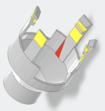
Since this has now largely become a 3D printing thread, I'd like to ask if any of you STL file creators know why the following model looks "transparent" in places...

Take note of this little arrow...

Now look at the view below and note how the arrow looks like it is suspended in mid air!

Got the STL file here:
(Created by Nick Gillard, who makes the Pico Mac Nano.)
I've been thinking about printing that yoke protector, now that I've removed my SE/30's CRT so as to install the LCD kit by @zigzagjoe .
@jmacz might have an opinion on this, because it sort of reminds me of the 040 heatsink clip with those arms that come down with hooks at the end. I should definitely avoid getting this printed in SLC Nylon at JLC.
Take note of this little arrow...
Now look at the view below and note how the arrow looks like it is suspended in mid air!
Got the STL file here:
(Created by Nick Gillard, who makes the Pico Mac Nano.)
I've been thinking about printing that yoke protector, now that I've removed my SE/30's CRT so as to install the LCD kit by @zigzagjoe .
@jmacz might have an opinion on this, because it sort of reminds me of the 040 heatsink clip with those arms that come down with hooks at the end. I should definitely avoid getting this printed in SLC Nylon at JLC.
James,This thread seems to have been 3D printing focused since Post #6.
But for a very logical reason. The topic of the CLEAR CASE from MacEffects naturally leads everyone to ponder the important bits which need to be made clear, such as the brightness knob...
View attachment 22209
And that brightness knob also pertains to the @zigzagjoe LCD Retrofit Kit. Doesn't need to be clear for the LCD Kit if you use the stock SE/30 case, and it does not even need to be 3D Printed at all if you use your existing knob. But if you want to retain your old Analog Board in complete condition, you would need a 3D Printed Brightness Knob (what we've been talking about of late), and also a 3D Printed Fan Mount too so you can mount a Noctua NF-A6x25 fan in it. (See also Instructions & Screws and the Forum writeup.)
View attachment 22217
But in terms of a CLEAR BRIGHTNESS KNOB, the photo above has a semi-transparent appearance similar to what I've had printed at JLC3DP in what they call "Translucent" 8001 Resin. It's foggy and not 100% clear like a MacEffects SE Clear Case. However, you can also order "Transparent" 8001 Resin prints...
View attachment 22213
See 32:56 in my video here to see JLC Translucent vs. Transparent.
But this brings us back to the topic of the tiny center piece with a split in the middle, which grabs onto the shaft of the Potentiometer. Will any of the JLC Resin offerings work without cracking? The answer will depend on how much that little center piece (with split in middle) FLEXES when the POT shaft is inserted into it. I know Nylon wouldn't break, but Nylon may actually be too flexible to make a good of the POT shaft!
It's very kind of @caver01 to have made the "Two in One" STL to get around JLC's frustrating minimum size requirement... FANTASTIC, in fact! But below are my observations about that.
OBSERVATION #1
The only transparent choice you have for FDM printing is TPU Translucent, but TPU is very rubbery and flexible, as far as I know (I've never tried it), and therefore I don't see how it would be suitable for a brightness knob (or would it?)...
View attachment 22214
OBSERVATION #2
It would seem to me that ABS would be stronger and more durable over time than PLA of the other FDM plastic options, and if that "guess" on my part is true, then you only have BLACK or WHITE as color options...
View attachment 22215
So I would love to hear discussion about what I said above, and then I can decide what to print for myself at JLC3DP.
And in regards to the Desk Saver Feet (to allow you to sit an SE or SE/30 with plastic case back OFF on your desk without worry of scratches, in what way is the new overhange converted to 45° version superior to the original? I printed the original in Nylon and had no issues with it in terms of getting the plastic SE/30 case-back on, but I will admit that I leave the metal shield off...
View attachment 22216
as for the clear resin durability question: you may want to reach out to Javier. I’m pretty certain he gets his clear 3D parts from PCBWAY. I have mice & joysticks from him that I’d think were injection molded if I didn’t know any better.
they are crystal clear & seem very strong to me…
I just realized I can RESIN CAST this part!! Hahahahaha! I can even tint one for my Blue MacEffects case too! I have a vacuum pot & pressure chamber.
I'd still like TWO, not THREE of your 3D printed ones, please!
I can't get into casting a test until I finish my Data General Dasher Terminal Recreation. It may be a while.
I'd still like TWO, not THREE of your 3D printed ones, please!
I can't get into casting a test until I finish my Data General Dasher Terminal Recreation. It may be a while.
I don’t know the root cause, but looked at the Printables item above. Looks great in their 3d viewer. Then I downloaded the STL and imported it into TinkerCAD. Check out the result:why the following model looks "transparent" in places...
So. . . this file has some issues, but of course you already know that. I have seen similar inconsistencies with how various 3d applications handle STLs from different sources. For example, I have downloaded STL files and even modified some myself that once brought into Prusa slicer are identified to have hundreds of “errors” that the slicer program “fixes”. Other examples I have seen don’t even get that far, like this CRT neck protector.
From what I have read, STL is a vector-like description of the outside faces of a 3d object. I have never actually looked at a file spec to understand how the triangles and vertices are specified or organized in this file format, but clearly there are different ways to interpret the data, or perhaps ambiguities that the various applications are resolving differently. My view here looks a little different than yours, which in turn looks different that the Printables vierwer—and I imagine different from the creator who actually exported it.
It probably deserves a bit of research into why, generally, STLs can have problems, depending on what app is being used to open them. I suspect it has to do with the original export.
SO, while I cannot explain how or exactly why you are seeing anomalies, I can at least confirm there is an issue. My issues viewed are not the same as yours, but I do have missing faces, triangles where there should be none, etc. BUmmer.
Perhaps there is a “fixer” or “repair” feature that can be used. I could try importing into Prusa slicer and see if it has issues, then re-export it to see what I get from that. It won’t have any generational quality loss, but it might re-arrange the data in the file in ways that remove ambiguities for other apps to misinterpret.
Well, here you go. Prusa Slicer auto-repaired 779 errors which does not surprise me since their online file viewer made the item look OK:

You can re-export an object from the slicer, so I did. Then imported it into TinkerCAD. It is fine now (in green):

Now, I don’t want to setup a file fix service any time soon, ha ha, but I attached a zip file containing my fixed version. Try loading that into your print service and see if it looks better. . .
You can re-export an object from the slicer, so I did. Then imported it into TinkerCAD. It is fine now (in green):
Now, I don’t want to setup a file fix service any time soon, ha ha, but I attached a zip file containing my fixed version. Try loading that into your print service and see if it looks better. . .
Attachments
There's definitely issues with the model that some slicers do not like. I tried to clean it up a bit and got better results with this STL from JLC3DP:Since this has now largely become a 3D printing thread, I'd like to ask if any of you STL file creators know why the following model looks "transparent" in places...
View attachment 22262
Take note of this little arrow...
View attachment 22263
Now look at the view below and note how the arrow looks like it is suspended in mid air!
View attachment 22264
Got the STL file here:
(Created by Nick Gillard, who makes the Pico Mac Nano.)
I've been thinking about printing that yoke protector, now that I've removed my SE/30's CRT so as to install the LCD kit by @zigzagjoe .
@jmacz might have an opinion on this, because it sort of reminds me of the 040 heatsink clip with those arms that come down with hooks at the end. I should definitely avoid getting this printed in SLC Nylon at JLC.
EDIT: OOF - looks like @caver01 beat me to it and his export is likely better than my recreation. His looks good in JPC3DP's analysis tool as well - I'd use his. I'm removing my STL to avoid confusion.
I didn't realize PrusaSlicer has a repair STL function, but apparently it does in the File menu. Thanks for the tip!
Last edited:
but apparently it does in the File menu
Will you look at that! Thanks for that tip. I have never used the repair function. I have only noticed the automatic repairs that appear in the right panel. Interesting. This must be a fairly widespread issue. By comparison, you don’t see a feature like this for .DOC or .XLS files in MS Office: “Repair Excel Spreasheet file. . .” I wonder why there are so many issues then with .STL.
I will say that when I have imported, adjusted, exported to print STLs and have these issues, I will sometimes export my adjusted versions to .obj which opens in my slicer too in order to get around a bad file issue.
I could not contain my curiosity, so I did a simple search and quickly found this page which seems to explain in rather good detail why we sometimes see issues with STL files for printing:
https://www.nano3dtech.com/p/problems-with-stl-files/
The upshot is that it is possible to model something in CAD software that results in issues for printing due to:
In my mind, the fault lies with the export—it seems some STL export processes are not perfectly catching or correcting some of the bullets above, or the developers are not designing their export feature with every use case for printing fully in mind.
The product manager in me wants to setup a simple use case—a model that exhibits exported issues to a printer/slicer, and hand that over to the developers to say, “see here, you have a case where your exported STL will cause issues for some slicers being used downstream.”
https://www.nano3dtech.com/p/problems-with-stl-files/
The upshot is that it is possible to model something in CAD software that results in issues for printing due to:
- Holes in the mesh can lead to weak spots in the printed object. The 3D printer may have difficulty interpreting where to deposit material, causing flawed or incomplete prints. If a hole appears on a curved surface, the software might even fill it incorrectly.
- Non-manifold edges (where there is not a clear indication what is INSIDE vs. OUTSIDE) will not slice correctly. A 3D printer requires clear instructions on what to print. Slicers don’t know how to deal with geometry that can’t exist in the real world. Non-manifold edges create ambiguities, leading to inconsistent surfaces that may result in printing errors.
- Self-intersections can create ambiguities in defining the volume of the object. They can create issues in how the printer interprets what needs to be filled or left empty. The slicing software may produce errant gaps or undesired solid regions.
- Degenerate triangles may create uneven or rough surfaces, causing inaccuracies in printed layers. Furthermore, degenerate triangles can even result in printing failures and aborted prints.
- Inconsistent normals (vector perpendicular to a face) can confuse a 3D printer on the surface orientation. When trying to print a hollow design with inverted normals, the printer can end up filling the inside of the shape.
In my mind, the fault lies with the export—it seems some STL export processes are not perfectly catching or correcting some of the bullets above, or the developers are not designing their export feature with every use case for printing fully in mind.
The product manager in me wants to setup a simple use case—a model that exhibits exported issues to a printer/slicer, and hand that over to the developers to say, “see here, you have a case where your exported STL will cause issues for some slicers being used downstream.”
@caver01
Incredible work and insight!
I downloaded your "macintosh_9inch_crt_cap_v1_FIXED.stl" just now, then uploaded it to JLC3DP here, clicked "Printing Risk" shown at left on their site, and see that all areas which were previously colored red with the original STL file (indicating 0.5mm or thinner) are now gone except for one oddball location shown below. It's strange only that one spot is red because I would assume a high degree of symmetry in that model.
Yeah, that is odd. When I have designed similar shapes with concentric cylinders, you don’t get infinite resolution. It is still broken down into facets. I know I am not using advanced CAD, so I don’t have direct control over arbitrary vertices for “smooth” shapes beyond being able to adjust the number of sides. Symmetry of the components like the finger clips may exist, but the number of sides for inner and outer sides of tubes as they get oriented in a circle may be different for different diameters, or may not line up the same with the other parts that extend from the rim.
While that protector is probably just right for the inner dimensions, I wish the whole thing was just a little thicker, or that the cone tip was not so narrow at the apex. I might try to print this myself.
While that protector is probably just right for the inner dimensions, I wish the whole thing was just a little thicker, or that the cone tip was not so narrow at the apex. I might try to print this myself.
@jmacz might have an opinion on this, because it sort of reminds me of the 040 heatsink clip with those arms that come down with hooks at the end. I should definitely avoid getting this printed in SLC Nylon at JLC.
That original STL file you linked in your post, I took a look at it and it seems it was generated in Blender.
I've seen a lot of great work done in Blender, but I have seen it used more for 3D modeling free form objects, figurines, artwork, something more unique, etc. Whereas for engineering projects it's usually done using a CAD program so that every aspect of the design is specified as a dimension / specification. While I don't personally use Blender, I have seen my kids use it to create some fantastic things (both for rendering and for 3D printing), but I have also watched HOW they use it and again, it's less precise, less specification/dimensionally driven, etc. Basically the workflow is less focused on dimensions and tolerances. If I was making a 3D articulated shark, I would use Blender. If I was making a very dimensional replacement part to be 3D printed or CNC machined on my mill, I would use a CAD program. You can make either type of object in either type of program, it's just the workflow is better (in my opinion) for the applications I mentioned. I normally use Fusion 360 for all my modeling because it's what I use for designing metal parts I mill on my CNC specifically because Fusion 360 also supports CAM which I need for my CNC machine. Professional machinists tend to use SolidWorks (and the other super expensive programs) while hobbyists like me also use AutoDesk's Fusion 360 or FreeCAD. No knock on Blender, I think it's awesome. I just find it easier to model mechanical parts in a CAD program.
Now that said, it comes down to how the part was designed regardless of program used. My guess is that some parts of the model were push/pulled in Blender to achieve a particular size and either a cavity/face was missed or something. Whereas in CAD, you would be designing that part using 2D profiles with mathematical dimensions to ensure there were zero thin walls, missing faces, etc. (ie. what you would see in an engineering diagram).
But I'm just guessing here.
as for the clear resin durability question: you may want to reach out to Javier. I’m pretty certain he gets his clear 3D parts from PCBWAY. I have mice & joysticks from him that I’d think were injection molded if I didn’t know any better.
I would expect most mass produced parts to be injection molded. But that is too involved/expensive for hobbyists (like me) to do for small quantities.
@JDW, resin is pretty strong depending on how it's cured and which resin you go with. Only issues why I don't use my resin printer often is the printable volume is much smaller (for the price), and it's such a hassle to use because of 1.) the initial prep work needed 2.) the post processing needed in terms of UV curing the model and cleaning it... and more importantly 3.) the time it takes to clean up the machine after you're done (takes 30+ minutes each time to do a good job given the resin is toxic). And if you have a failed print half way through, you have to drain the vat and basically clean most of the machine to prevent leaving any parts that half formed in the vat, before you try again.
That said, I have printed the following type of things via resin (using a "tough" resin) and they came out very precise and strong:
- New magneto optical drive bezel for my Quadra 800
- New front drive slot cover for an SE (with a square notch for the LED just like stock)
- New programmers switch for the SE or SE/30
- New programmers switch for the IIci (tons of curves in the model as you know)
- New front bezel for my PowerBook 540c (the little round cover under the LCD with the microphone hole in it)
- New battery slot covers with working switch for my PowerBook 540c
- Light tube for the hard disk LED in my SE (that fits into the square notch in the slot cover I mentioned above)
- Light tube for my Macintosh II drive cover
- Various other light tubes
But crystal clear 3D printed parts are achievable with resin printing.
Last edited:
I've had oddities like this in multiple prints at JLC3DP and I've just accepted the risk and never had uses with the outcome. I'm sure there is some risk that the model is not correct, but I'm guessing that would be fine to print.@caver01
Incredible work and insight!
I downloaded your "macintosh_9inch_crt_cap_v1_FIXED.stl" just now, then uploaded it to JLC3DP here, clicked "Printing Risk" shown at left on their site, and see that all areas which were previously colored red with the original STL file (indicating 0.5mm or thinner) are now gone except for one oddball location shown below. It's strange only that one spot is red because I would assume a high degree of symmetry in that model.
View attachment 22291
TANGENT/
IF
two metal rings replace yellow band on outside of knob
OR
flange added to place two metal rings on backside of flange face
AND
matching brushes placed on PCB Controller board mounted on barely visible lower corner of A/B
AND
mounting point for full spectrum LED provision made inside clear/slightly fogged print . . .
. . . Multi-Hued Light Show in my clear case with knob rotated or not . . .
/TANGENT
edit: waking up a bit: ring shaped PCB is likely the best way to put 2 (3?) copper tracks on rear face of knob for full spectrum interface?
Last edited:
OK, so the package arrived this afternoon. They look pretty good - certainly not perfectly clear (I think JLC3DP may not do as good of a job with the oil coating or sanding in crevices - which is understandable). But I think it is a worthwhile upgrade if you really want to maximize the transparency in your new case.
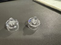

Installation went well. They definitely are a tighter fit and I'm not sure I was able to get it installed on the pot as deeply as the original, I was worried that may not allow the analog board to be installed as deeply. It also took a good bit of pressure to get it to go in as much as I did. I pinched it with the back of the pot because if you pushed it certainly would have bent it backwards. However, I don't know if the fact it isn't installed as deep, or if the resin doesn't move smoothly (does the nub on the original actually make contact with the little socket on the front of the case?), but the knob is definitely harder to turn. It's pretty stiff, but still possible, and I don't change the brightness often enough where that will bother me.
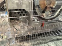
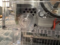
And, while it was off, I installed the new transparent BlueSCSI mount. Works perfectly.
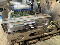
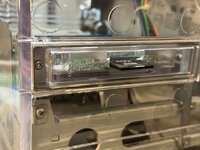
If everyone is still in, I can order a new batch with the latest model. If everyone has concerns about the tightness of the fit, maybe we can discuss with @caver01 to make one with a bit larger opening for the pot's arm.


Installation went well. They definitely are a tighter fit and I'm not sure I was able to get it installed on the pot as deeply as the original, I was worried that may not allow the analog board to be installed as deeply. It also took a good bit of pressure to get it to go in as much as I did. I pinched it with the back of the pot because if you pushed it certainly would have bent it backwards. However, I don't know if the fact it isn't installed as deep, or if the resin doesn't move smoothly (does the nub on the original actually make contact with the little socket on the front of the case?), but the knob is definitely harder to turn. It's pretty stiff, but still possible, and I don't change the brightness often enough where that will bother me.


And, while it was off, I installed the new transparent BlueSCSI mount. Works perfectly.


If everyone is still in, I can order a new batch with the latest model. If everyone has concerns about the tightness of the fit, maybe we can discuss with @caver01 to make one with a bit larger opening for the pot's arm.
That’s interesting about the tightness after re-assembly. Here‘s that same ORIGINAL model installed on the board for which it was made. I know the model works for FDM parts just great:
:

You can see that the back rim very nearly touches the pot. If you slide the post of the pot into the knob all the way home, this is how it should sit. The post receiver/sleeve is supposed to grip, but has the splits so that it can flex just a little. Of course this is exactly like the original.
Did your combined version of my model lose any depth in the receiver/sleeve that would prevent it from going all the way on?
I am afraid that if the knob sits too proud, the face of the shell is compressing against the knob. There is a receiving round ring/hole which I am sure you have seen, but it’s not really size matched to act as a bushing. it s more for alignment, and as it is too big to really hold the knob tip tightly, it provides strain relief only if someone really pushes up hard on that thing. I suspect you are compressing the knob into that ring in the face of the shell.
I am only starting the migration process on my SE/30. . . still awaiting a BlueSCSI2 board, so you are a bit ahead of me. It is going to be some time before I am removing the analog board on my setup, but since I have used this part before, I thought the picture might help.
I wonder if the resin print just comes out thicker for inner dimension tolerances. If you have enough depth, you could try sanding or dremeling out the post receiver a bit. I know, it messes up the clarity, but where it touches the metal pot post does it matter? Just an idea.
If, in the end, we decide a resin part simply has different tolerance needs, I am happy to adjust a version for that but it would be trial an error.
:
You can see that the back rim very nearly touches the pot. If you slide the post of the pot into the knob all the way home, this is how it should sit. The post receiver/sleeve is supposed to grip, but has the splits so that it can flex just a little. Of course this is exactly like the original.
Did your combined version of my model lose any depth in the receiver/sleeve that would prevent it from going all the way on?
I am afraid that if the knob sits too proud, the face of the shell is compressing against the knob. There is a receiving round ring/hole which I am sure you have seen, but it’s not really size matched to act as a bushing. it s more for alignment, and as it is too big to really hold the knob tip tightly, it provides strain relief only if someone really pushes up hard on that thing. I suspect you are compressing the knob into that ring in the face of the shell.
I am only starting the migration process on my SE/30. . . still awaiting a BlueSCSI2 board, so you are a bit ahead of me. It is going to be some time before I am removing the analog board on my setup, but since I have used this part before, I thought the picture might help.
I wonder if the resin print just comes out thicker for inner dimension tolerances. If you have enough depth, you could try sanding or dremeling out the post receiver a bit. I know, it messes up the clarity, but where it touches the metal pot post does it matter? Just an idea.
If, in the end, we decide a resin part simply has different tolerance needs, I am happy to adjust a version for that but it would be trial an error.
I measured and the only difference in depth between the resin part and the original was that the original has a deeper hole in the center. But as your printed version doesn't have that and still sits flush, I don't think that is the problem (and the fact that the arm the knob sits on doesn't have a small protrusion that would go in that little hole.That’s interesting about the tightness after re-assembly. Here‘s that same ORIGINAL model installed on the board for which it was made. I know the model works for FDM parts just great:
:
View attachment 22302
You can see that the back rim very nearly touches the pot. If you slide the post of the pot into the knob all the way home, this is how it should sit. The post receiver/sleeve is supposed to grip, but has the splits so that it can flex just a little. Of course this is exactly like the original.
Did your combined version of my model lose any depth in the receiver/sleeve that would prevent it from going all the way on?
I am afraid that if the knob sits too proud, the face of the shell is compressing against the knob. There is a receiving round ring/hole which I am sure you have seen, but it’s not really size matched to act as a bushing. it s more for alignment, and as it is too big to really hold the knob tip tightly, it provides strain relief only if someone really pushes up hard on that thing. I suspect you are compressing the knob into that ring in the face of the shell.
I am only starting the migration process on my SE/30. . . still awaiting a BlueSCSI2 board, so you are a bit ahead of me. It is going to be some time before I am removing the analog board on my setup, but since I have used this part before, I thought the picture might help.
I wonder if the resin print just comes out thicker for inner dimension tolerances. If you have enough depth, you could try sanding or dremeling out the post receiver a bit. I know, it messes up the clarity, but where it touches the metal pot post does it matter? Just an idea.
If, in the end, we decide a resin part simply has different tolerance needs, I am happy to adjust a version for that but it would be trial an error.
I suspect the resin prints in 8001 resin have different tolerances. I notices it when I printed clear resin versions of the cases for my HDI-45 adapters. The sold, white resin cases had a much easier fit than the 8001 clear resin. I may try to play around with dremelling out the inner area. I do wonder if a version with a larger opening would be best.
I'm guessing, based on how far away mine was to be fully inserted like you have in your picture, that I only inserted it up to where the relief slots end. I'm guessing the slots to allow it some give, enough for me to push it in, but where the insert is surrounded by the knob, it cannot expand and there simply is not enough room. The more I think about it, the more likely I'd be to shave off a bit of the arm on the pot to fit, rather than trying to shave off the inside of the knob. But I understand why others would be less likely to want to try that.
If everyone is fine with waiting, I could do another small run just to keep costs down if the next iteration doesn't work better. Would you be able to make a version with a slightly larger hole to see if we could get it dialed in on that specific resin?
Of course. . . Any suggestions on how much more room you might need?Would you be able to make a version with a slightly larger hole
The original round hole is exactly 6.00mm. The flat encroaches another 1.75mm from the I.D.
Last edited:
