@David Cook
One of the reasons I make detailed videos is because I am often in need of detailed help. I try to help people the way my feeble brain needs to be helped. You are providing kind of excellent help, step-by-step. It's crystal clear. Thank you!
Admittedly, I've not had the need to play with the oscilloscope
MATH function before, but I am pleased at this new opportunity. I won't have time to test the Portable until tonight, after work. But I did a quick set of baseline tests this morning to establish the
noise floor as described below.
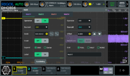
Here are my scope settings that are accessed when pressing the MATH button, made in accordance with your earlier suggestions:
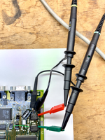
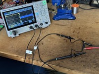
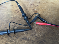
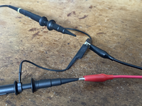
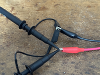
Below is a photo of my noise floor test setup. Both Probes are switched to 10x, and the scope is manually set to 10x for each probe (an important consideration since my scope doesn't automatically detect the 1x / 10x slide switch on the probes.)
The photo below also shows both GND leads on each probe connected to eachother. The scope itself is NOT connected to wall-socket EARTH ground, hence it is a "floating scope." Probe tips are initially not connected to anything.
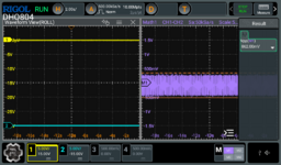
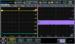
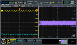
Here's the scope display with both probes disconnected (but their ground leads connected to eachother only):
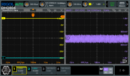
So with both probes DISCONNECTED (only GND leads connected to eachother), the A-B math function shown in purple at right (in the above) has a noise floor of about 768mV, but that fluctuates and sometimes is more than 800mV.
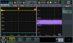
I then connected both Probes to eachother, leaving their Grounds connected to eachother, and I also connected the Ground lead of my Function Generator too. (The red wire below is the Function Generator output wire, which is disconnected.) As you can see below, the noise floor remains the same (which is what you would expect):
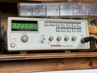
For a simple test, I set my Function Generator to output a 3.2kHz SINEWAVE:
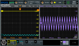
I then connected only Probe-2 to that SINEWAVE output, which displays on the scope like this:
After that, I connected Probe-1 also to the same SINEWAVE, which cancels out eachother and leaves only the Noise Floor we saw earlier:
So unless you see me doing something wrong in the above, what I will do during my Portable test tonight is the following (based on your advice):
- Put CH1 probe on U15B pin 12.
- Put CH2 probe on U15C pin 12.
- Connect both Probe GROUND leads to the same ground on the Portable's motherboard.
- Power on the Portable, then do various tests (booting, etc.) and see how the scope display changes, if at all.

