Macintosh Portable: "pop" noise every 10s from Speaker & Headphones

Androda

TinkerDifferent Board Secretary 2023
Staff member
Sep 25, 2021
496
531
93
USA, Western
androda.work
As you can see, 5.29v. Is that voltage level normal
Normally the main power rail is intended to be at 5.2v. But I've seen these systems at 5.15v, 5.26v, etc.

The hybrid module's feedback resistors are, I believe, mostly 1% or 0.5% tolerance. 5.3v is 1.9% different than 5.2v, and not likely to be an issue. But it does show a little drifting, which I suppose is to be expected from these old components.

In other words, if the Portable's power regulator is working properly then it makes no difference whether a Battery Eliminator is in use.
 
  • Like
Reactions: JDW

JDW

Administrator
Staff member
Founder
Sep 2, 2021
1,577
1,373
113
53
Japan
youtube.com
@Androda , thank you for your kind feedback. I appreciate the insight.


The video below shows what activates the soft pop every 10 seconds — merely booting! You can also hear how the noise changes, even when you open or close a window while at the Desktop.

It would be greatly appreciated if you could please watch the video below, cranking your volume up sufficiently to hear the noise (after I've booted the machine), and then let me know your thoughts. More specifically, if you have any ideas on what I should probe on the motherboard to further track down the source of the noise, I'm truly "all ears"! :) Thanks!


David Cook

New Tinkerer
Jul 20, 2023
24
22
3
Feedback from the LCD driver rather than the code that is running? Notice that the sound changes exactly as the screen changes images. "Welcome to Macintosh" (whine changes) "gray before Finder appears" (whine changes) "Finder window appears" (whine changes) "Chooser appears" (whine changes) "Chooser goes away" (whine changes). It seems related to the amount of white pixels on the screen.

If you open TeachText and make the window smaller and bigger (to change the amount of white pixels), does the whine change? Then you'll know it isn't code -- it's the LCD driver.
 

JDW

Administrator
Staff member
Founder
Sep 2, 2021
1,577
1,373
113
53
Japan
youtube.com
If you open TeachText and make the window smaller and bigger (to change the amount of white pixels), does the whine change? Then you'll know it isn't code -- it's the LCD driver.
Let’s assume for the moment that it is, as you say, the “LCD driver.“ What then must I do?
 

David Cook

New Tinkerer
Jul 20, 2023
24
22
3
My hope is that if you can reproduce this on demand by varying the pixels on the display, it:
1. May help you follow the noise through the circuit.
2. May suggest a problem with the LCD grounding/filtering
3. May suggest there is a grounding or filtering issue on the sound circuit, as opposed to a bad chip. This is my best guess.
 
  • Like
Reactions: ppuskari and JDW

nottomhanks

Tinkerer
Oct 31, 2021
119
51
28
I just watched some of the video, and my experience has been that excess noise or whining comes from the LCD backlight, but I have NOT listened through headphones. I'll have to take a listen to that output, and I can also record the output and see if there's any pops or clicks happening. Wondering if these noises are just manifesting through the speaker, but not the headphone output.

Very interesting.
 
  • Like
Reactions: JDW

SuperSVGA

Tinkerer
Mar 26, 2022
64
34
18
The video below shows what activates the soft pop every 10 seconds — merely booting! You can also hear how the noise changes, even when you open or close a window while at the Desktop.

It would be greatly appreciated if you could please watch the video below, cranking your volume up sufficiently to hear the noise (after I've booted the machine), and then let me know your thoughts. More specifically, if you have any ideas on what I should probe on the motherboard to further track down the source of the noise, I'm truly "all ears"! :) Thanks!
I tried booting from that same French MacTest Portable disk on mine and seem to have the exact same sound every 10 seconds. Yet if I boot from a System 6.0.8 "System Tools" disk that sound does not occur.
 
  • Like
Reactions: JDW

JDW

Administrator
Staff member
Founder
Sep 2, 2021
1,577
1,373
113
53
Japan
youtube.com
Wondering if these noises are just manifesting through the speaker, but not the headphone output.
The speaker is mono while headphones are stereo. The speaker also attenuates noise more than headphones. For those two reasons, I cannot hear all that noise as easily through the mono speaker as I can through headphones. With that said, I can hear that pop sound every 10 seconds from the mono speaker too, which is really what set me on this desperate quest to get rid of tht pop sound.

Being able to address other noise issues too, would make the headphone jack more usable. So far though, I only have a small data pool of people who have tested their Portables, so it's hard to establish a baseline noise level we can call "normal."

I tried booting from that same French MacTest Portable disk on mine and seem to have the exact same sound every 10 seconds. Yet if I boot from a System 6.0.8 "System Tools" disk that sound does not occur.
Very interesting. Thank you for doing that test.

I will boot from a S6.0.8 floppy tonight after work and let you know what happens with that.
 

JDW

Administrator
Staff member
Founder
Sep 2, 2021
1,577
1,373
113
53
Japan
youtube.com
@SuperSVGA
I tested just now by booting from disk-1 of the System 6.0.8 floppy installation disks (via my FloppyEMU). Like you, I did not hear the pop every 10 seconds. However, when I copied the "Portable" control panel to that floppy and restarted, then I then heard the pop every 10 seconds! That control panel let's you adjust things like the sleep timer and either contrast or backlight brightness, depending on which version "Portable" control panel you use. I used the newest one that lets me control the backlight brightness or kill the backlight altogether.

This test seems to prove the Portable control panel is the source of the pop every 10 seconds.

@nottomhanks
Changing brightness of the backlight or disabling it altogether has no impact whatsoever on the pop every 10 seconds or the noise I head in my headphones.

@David Cook
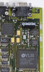
Not sure where to begin tracing the noise, but as you read in my paragraphs above, what is displayed on the LCD alters the noise. Interestingly, the big VLSI chip marked VIDEO (U15D) is on one side of the audio circuitry, and the VIDEO output connector is on the other side (although I am not connecting anything to that VIDEO connector).

1711537112553.png
(Photo above shot by @Branchus — that is not a photo of my board)

More info...

If I double-click my boot disk to open a window, then expand that window to fill the screen (so the screen is mostly white), the whine goes away. There is still noise, but I am talking about the whine in the Right channel.

Also, if you go to the Apple menu and choose something like About this Macintosh, then you will hear more noise through your headphones. Well, at least I am hearing more noise. Not sure about the rest of you.

Stacking multiple windows seems to increase the noise more.

Not sure how to make sense of the above. It's all FYI. Hopefully, somebody much smarter than me can figure it out. I'd love to hear everyone's thoughts in light of this.
 

ppuskari

Tinkerer
Dec 25, 2021
21
25
13
I can't add too much at all to this but soaking it all in for potential usage when I tackle my own 5126 machine. Mines recapped but still has a bad power handler since it will not power up a SCSI drive except for the low power scsi2sd. I got it used and that is okay. At least I got one in my collection that was supposedly recapped already. I can say though, that once these are figured out, I may have to apply some of the fixes if they make sense to a test Apple IIGS Rom 01 motherboard or two. Sound blips are a known and continuous issue as the 12v gets blipped up for 3.5" and 5.25" drive polling. The issue with whine on video changes is also a known affliction and was more or less tamed with the Rom 3 redesign but still not perfect. Interesting that Apple carried along the same noise level designs across multiple machines/platforms even.
 

David Cook

New Tinkerer
Jul 20, 2023
24
22
3
1711572023926.png


I suspect the LCD electrical noise is being injected (or not filtered) in the above area of the circuit.

Here's what I would check:
1. Obviously look carefully for loose pins or corrosion in this area. I suspect you've already done this. Any resistance on the ground or power supply connections to the right chip would certainly allow the injection of nearby circuit noise.

Here's the part that relies on the right channel producing a different output than the left channel.
2. Using an oscilloscope in math-subtract mode, measure pin 12 of both chips at the same time (one probe on U15B pin 12, the other probe on U15C pin 12, the ground connected to the same ground point). You should see a flat line as there should be almost no difference on the voltage supplied to both chips. Math mode is key as it subtracts one signal from the other and you don't have to compare the two waveforms by eye. A multimeter or single probe multimeter is not going to cut it for these tests.

3. Repeat on pin 13, 15, and 17. These are all power related lines and should be identical for both chips. If noise is present in the power to the sound chip, it stands to reason it would affect the sound output.

4. Repeat on pin 18. This is the data input to the sound chips. Let's hope the difference isn't here. Otherwise the issue is upstream.

5. Repeat on pin 11. Repeat C9-here-R90 (left) vs C10-here-R77 (right). Repeat L1 pin 1 (left) vs L1 pin 3 (right). These are all post sound chip areas whose purpose is to remove the DC voltage from the signal. If one of these components is bad or weakly connected, it could do a poor job removing circuit noise.

My hope is that you're going to find a big noisy waveform in one the differential tests.

- David
 
Last edited:

JDW

Administrator
Staff member
Founder
Sep 2, 2021
1,577
1,373
113
53
Japan
youtube.com
Sound blips are a known and continuous issue as the 12v gets blipped up for 3.5" and 5.25" drive polling.
Do you have a source/link to that being a "known issue"? Also, the recent testing I am doing and reporting on is without the hard drive and without a real floppy drive attached at all. Earlier, I specified that I wasn't even using a FloppyEMU (although I don't get the pop every 10 seconds in that case). And later I specified I was using a FloppyEMU (lower power than a real floppy drive, and which uses only 5V, I believe), to boot from virtual disk images. And as mentioned in my previous post, I only get the pop every 10 seconds if the "Portable" control panel is installed.

The issue with whine on video changes is also a known affliction and was more or less tamed with the Rom 3 redesign but still not perfect. Interesting that Apple carried along the same noise level designs across multiple machines/platforms even.
Again, do you have an official source that states "whine is a known issue" on all Macintosh Portables, including the 5120 and 5126?

Right now, the data pool of people who have tested their 5120 or 5126 after reading my posts is tiny, consisting of only two people. Having more people test, especially listening to headphones at the headphone jack where noise is much more easily identified, is important and useful information. So whenever you have your machine running well, I would be interested in hearing how much noise your machine has, under various conditions.

2. Using an oscilloscope in differential mode...
David, thank you for the detailed advice. I don't have any expensive differential probes, but to date, I have been testing with a floated scope, meaning that the Earth ground of the scope has been disconnected. For small signal voltage measurements like I am doing, that is not a big issue regarding safety. It's mainly an issue when testing voltages above 60V, which don't apply here.

My scope is a 4-channel 70MHz Rigol DHO804, hacked to 100MHz bandwidth and 50Mpts memory.
 

David Cook

New Tinkerer
Jul 20, 2023
24
22
3
I don't have any expensive differential probes, but to date, I have been testing with a floated scope, meaning that the Earth ground of the scope has been disconnected.

Your Rigol scope is perfect for this test. For this, we care about the scope feature, not the probes.

I assume both of your probes are in 10:1 configuration?
Put the CH1 probe on U15B pin 12.
Put the CH2 probe on U15C pin 12.
I guess connect the ground of both probes together. Funny, I haven't used a floating ground before.

Press the Math button. Operator A-B. Operation ON. Source A = CH1. Source B = CH2. Adjust the Scale as desired.

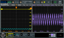
In my example below, my probes are connected together. The vertical positions of the blue line and yellow line are purely GUI features so that each probe can be seen. Also notice that CH2 is at 500 mV because I want to show that the math function does not care about the display values. It only cares about the actual signals coming in.

Regardless, the purple line is the difference between the probes at a 100 mV scale. There is some inherent noise. Don't be fooled into thinking this is from your circuit. So, test the probes together first to get a sense for "normal" noise. Then test them on the Macintosh Portable. Hopefully you'll find a pair of test points where there is a substantial difference where there shouldn't be.

1711577956919.jpeg
 

David Cook

New Tinkerer
Jul 20, 2023
24
22
3
I don't have any expensive differential probes

I have edited my prior message to now say 'math-subtract' mode to avoid confusion for future readers. Originally, I used the word 'differential' which may not be the right terminology.
 
  • Like
Reactions: JDW

JDW

Administrator
Staff member
Founder
Sep 2, 2021
1,577
1,373
113
53
Japan
youtube.com
@David Cook
One of the reasons I make detailed videos is because I am often in need of detailed help. I try to help people the way my feeble brain needs to be helped. You are providing kind of excellent help, step-by-step. It's crystal clear. Thank you!

Admittedly, I've not had the need to play with the oscilloscope MATH function before, but I am pleased at this new opportunity. I won't have time to test the Portable until tonight, after work. But I did a quick set of baseline tests this morning to establish the noise floor as described below.

Here are my scope settings that are accessed when pressing the MATH button, made in accordance with your earlier suggestions:
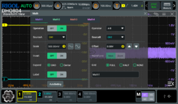
Math_Settings.png

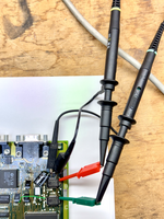
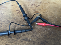
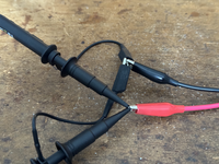
Below is a photo of my noise floor test setup. Both Probes are switched to 10x, and the scope is manually set to 10x for each probe (an important consideration since my scope doesn't automatically detect the 1x / 10x slide switch on the probes.)

The photo below also shows both GND leads on each probe connected to eachother. The scope itself is NOT connected to wall-socket EARTH ground, hence it is a "floating scope." Probe tips are initially not connected to anything.
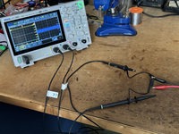
tempImageeF4Cr3.png

Here's the scope display with both probes disconnected (but their ground leads connected to eachother only):
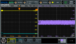
Both_Probes_Disconnected.png

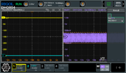
So with both probes DISCONNECTED (only GND leads connected to eachother), the A-B math function shown in purple at right (in the above) has a noise floor of about 768mV, but that fluctuates and sometimes is more than 800mV.
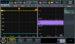
NoiseFloor_ProbesDisconnected.png

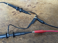
I then connected both Probes to eachother, leaving their Grounds connected to eachother, and I also connected the Ground lead of my Function Generator too. (The red wire below is the Function Generator output wire, which is disconnected.) As you can see below, the noise floor remains the same (which is what you would expect):
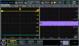
tempImageqHfQ77.png BothProbes_Connected_to_EachotherOnly.png

For a simple test, I set my Function Generator to output a 3.2kHz SINEWAVE:
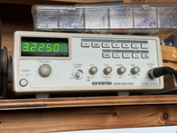
tempImage5RWrVa.png

I then connected only Probe-2 to that SINEWAVE output, which displays on the scope like this:
tempImagebnIlzv.png Probe2_connected_to_SINEWAVE.png

After that, I connected Probe-1 also to the same SINEWAVE, which cancels out eachother and leaves only the Noise Floor we saw earlier:
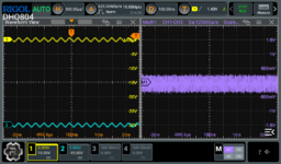
tempImageewhnCs.png BothProbes_Connected_to_SINEWAVE.png

So unless you see me doing something wrong in the above, what I will do during my Portable test tonight is the following (based on your advice):
  • Put CH1 probe on U15B pin 12.
  • Put CH2 probe on U15C pin 12.
  • Connect both Probe GROUND leads to the same ground on the Portable's motherboard.
  • Power on the Portable, then do various tests (booting, etc.) and see how the scope display changes, if at all.
 

David Cook

New Tinkerer
Jul 20, 2023
24
22
3
Although the setup looks correct, the 800 mV noise floor is freaking me out. It should be an order of magnitude lower. Am I being tricked by the 10x probe?

In any case, you definitely see the difference in the final two images from the scope. Even if the scale is off or the base noise is higher than I expect, if this tool works to catch the location of the differences in your sound channel -- then it works!
 

YMK

Active Tinkerer
Nov 8, 2021
358
285
63
Zooming way out on the time scale (2 sec/div) might help correlate the noise to the audible ticks.
 

JDW

Administrator
Staff member
Founder
Sep 2, 2021
1,577
1,373
113
53
Japan
youtube.com
Am I being tricked by the 10x probe?
Not sure about being tricked, but the two probes are indeed set to 10X, and the scope setting for each probe is also set to 10X. There is no mistake about that.

With that said, I often use 1X when I measure very small signals. For example, if I want to measure ripple riding on the 5V output of a switching power supply, I would absolutely use 1X and then make sure I am using AC coupling.

By the way, I used DC coupling for everything mentioned in my previous post.

Zooming way out on the time scale (2 sec/div) might help correlate the noise to the audible ticks.
Thereby, making peaks in the audio theoretically easier to spot. Understood.

It also shows a raised noise floor because it detects all the extreme peaks over a longer period of time...

2s-per-div.png
(Above screenshot made with both probes connected to eachother and not connected to anything else.)
 

JDW

Administrator
Staff member
Founder
Sep 2, 2021
1,577
1,373
113
53
Japan
youtube.com
CORRECTION: The suggestion to measure "pin 12" of UB15B and UB15C was incorrect. Pin 12 is SONY_+12. The pins I need to probe with my scope are 11, shown in yellow below.

1711618457963.png


tempImageyxKagg.png