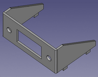
@phipli absolutely love your work here, but scale is problematic.
View attachment 19347
Your lug holes will be nearly tangential to the bend lines on the sides. Nuts won't work and I don't think heavy enough metal to tap would be a workable alternative. Too much work even if possible.
I'm wondering if the shield slots are large enough to heat/moldover/weld(?) pins on the bottom of a printed chassis to the bottom of the PCB? Can't remember the name of the process Apple used to attach heat shields parts to case plastics.
Anyway, drilling the slots out to round and bolting up a printed chassis for the connector ought to work fine?
I'm afraid that I don't quite follow, the issues you raise aren't things that I was worried about and I'm not 100% sure which features you mean - regional dialects can vary a lot for this sort of thing - lug can mean several things, in this context it could mean the threaded parts that go through the VGA port, or the four tabs for the bracket itself - it isn't usually a technical term except in the context of cable mounting lugs perhaps. I'd been worrying about a some difficulties, like corrosion prevention, thermal mass, and order of operations, but the first - you can plate at home, the second, pre-heating and a good iron, and the third I'd worked out a workable order.
Are you worrying about distortion due to the proximity of the VGA ports mounting hole to the fold? That shouldn't be an issue, the face with the openings can be clamped during the fold, or alternatively the holes can be drilled after the folding is complete.
Threading? Nothing on the part needs threading? I'm not quite sure where you mean? It sounds like you mean into the four tabs... but that isn't what they're for - they're for soldering. The thing I'm wondering here is if I'd need to go down to 0.6mm steel to help with the thermal mass. The thinner the metal used, the more critical the extra fold in the third picture I put in the post afterwards becomes, that is for rigidity. I'd fold it with extra length, and then cut it down afterwards - it is difficult to fold things without sufficient material.
Dimensions on the mounting face are vaguely accurate (I measured connectors with a ruler), to build I'd measure accurately and prototype in cardboard. But the tabs that go into the PCB have just been guessed, and the length of the two... "wings" have only been eyeballed. My 6100 is in use so I'm not able to take measurements atm.
Some of the other things you've mentioned, I realise I probably haven't specifically mentioned it, but my intention was to solder the bracket in place, in a similar manner to how most ports are mounted on a mac.
A 3D printed part could potentially be fixed by applying heat to the four tabs like you say, but I don't have a 3D printer - I'm more of a metal kind of person.
Really sorry if I'm misunderstanding, well, I know I am, I don't quite follow your post.
 Just gotta love that beautiful mess. Haven't done the pin count, are those PCI slots?
