Need solution for HDI-45 to DB-15 connectors for video out

Trash80toG4

Active Tinkerer
Apr 1, 2022
953
273
63
Bermuda Triangle, NC USA
A 3D printed part could potentially be fixed by applying heat to the four tabs like you say, but I don't have a 3D printer - I'm more of a metal kind of person.

Really sorry if I'm misunderstanding, well, I know I am, I don't quite follow your post.
Sorry about that, I have trouble using language to describe things. Visual thinking has its drawbacks. I'll do a graphic later tonight or tomorrow.

Just put a caliper on the parts. the circles on your diagram need to be set apart about 29.12mm, outside edge to outside edge.
The inside "diameter" would be only about 28.41mm, to narrow to be workable as is.

about like this:

|O-----------O|

but the holes would be much closer yet to being tangential to the sides. Your diagram is about like this:

|-O---------O-|

Is that helpful?

edit: just enough time before work to take a really bad pic.

View attachment 19357
 
Last edited:

phipli

Tinkerer
Sep 23, 2021
192
150
43
Sorry about that, I have trouble using language to describe things. Visual thinking has its drawbacks. I'll do a graphic later tonight or tomorrow.

Just put a caliper on the parts. the circles on your diagram need to be set apart about 29.12mm, outside edge to outside edge.
The inside "diameter" would be only about 28.41mm, to narrow to be workable as is.

about like this:

|O-----------O|

but the holes would be much closer yet to being tangential to the sides. Your diagram is about like this:

|-O---------O-|

Is that helpful?

edit: just enough time before work to take a really bad pic.

View attachment 19357
The cad model has 26mm between the two screw centres on the connector. That is 1mm oversize vs what they actually should be (like I said, I measured with a ruler quickly to get a visual representation rather than a final design).

1736702269504.png


I realise that is a 9 pin part, but the bodies are the same as for the VGA HD part.

The opening I made for the actual electrical part of the connector is about 1mm undersize. Between the two 1mm errors, the holes will be 1mm too far from the connector... for a graphical representation it was close enough isn't it? I'm confused.
 

Trash80toG4

Active Tinkerer
Apr 1, 2022
953
273
63
Bermuda Triangle, NC USA
Thanks for the graphic! Center to center isn't the concern, width of the holes from outside edge to outside edge relative to inside to inside edge of your part is the issue.

I'll do an AI session tonight. ;)
 

phipli

Tinkerer
Sep 23, 2021
192
150
43
width of the holes from outside edge to outside edge relative to inside to inside edge of your part is the issue.
But.. That doesn't matter? That doesn't have any impact?

The VGA connector is inside the case? As long as the VGA cable end goes through the huge opening in the rear of the case, there isn't an issue? I'm confused again.

I guess you're seeing something I'm not, I'll leave you too it and see what you're working on.

Edit - I'm really struggling with your phrasing there... width of a hole? You mean diameter? Outside edge of what? Inside edge of what?
 

phipli

Tinkerer
Sep 23, 2021
192
150
43
Ah, do you mean that the VGA connector is wider than the bracket?

You can fit it to the outside of the bracket. But also the bracket is 35mm wide and the VGA connector is about 31mm wide.
 

Trash80toG4

Active Tinkerer
Apr 1, 2022
953
273
63
Bermuda Triangle, NC USA
inside to inside measurement of the bracket is more like 28.mm, not 35mm.

At its widest point at the front, where the edges of the sides are stamped outward from what the sides of your bracket would be, it's only about 30.8mm outside to outside.

Deleted/reposting pic from above for rough connector to connector comparison:

P1000729.JPG

So I don't have to unearth mine, what's the width of the opening at the back of the case for this horrid connector?
 
Last edited:

phipli

Tinkerer
Sep 23, 2021
192
150
43
inside to inside measurement of the bracket is more like 28.mm, not 35mm.

At its widest point at the front, where the edges of the sides are stamped outward from what the sides of your bracket would be, it's only about 30.8mm outside to outside.

Deleted/reposting pic from above for rough connector to connector comparison:

View attachment 19359

So I don't have to unearth mine, what's the width of the opening at the back of the case for this horrid connector?
Ah, excellent, I understand what you mean now.

My measurement was over the plastic housing on the connector, which is the size of the recess in the back of the machine, but not the opening, which a quick check with a plastic ruler says is about 32mm like @wottle says.

That's fine, looks like things could still be made to fit, especially if you align the metal bracket with the rear of the case so that it is flush with the opening in the case. Or we could just use a PCB and place the VGA connector far back enough towards the case opening that it overhangs the edge of the logic board and doesn't clash with the HDI45 pins at all, as previously discussed. It looks like there is room. But, I think we're getting a little bogged down in the details of the dimensions of what was a 3D concept sketch. The best way to design the part is by building something, for example out of a bit of cardboard.
 

Trash80toG4

Active Tinkerer
Apr 1, 2022
953
273
63
Bermuda Triangle, NC USA
Ah, excellent, I understand what you mean now.
Great, glad I could get it straightened out for you.

My measurement was over the plastic housing on the connector, which is the size of the recess in the back of the machine, but not the opening, which a quick check with a plastic ruler says is about 32mm like @wottle says.
@wottle thanks for that info. Yep, not being on the same page in terms of dimensions is problematic.

I think we're getting a little bogged down in the details of the dimensions of what was a 3D concept sketch. The best way to design the part is by building something, for example out of a bit of cardboard.
Cardboard is a great idea, that's how I make prototypes for my riser projects, but they're flat, no bends. There's a better approach for modeling this one I think. Check out the roofing section of Lowes or Depot and pick up a piece or two of Step Flashing, which is thin aluminum, very easily bends in straight lines if scored slightly with fingers or pliers and holds its shape. I use it for all kinds of stuff, like ductwork in my hacks.
 

phipli

Tinkerer
Sep 23, 2021
192
150
43
but they're flat, no bends.
Oh, I mean literally make the part in 3D with cardboard. All of the bends, none of the flat.

The nearest Lowes or Depot is several thousand miles away for me :ROFLMAO: I do have some sheet aluminium in the other room though, but the price of it I'd rather use cardboard and sticky tape :LOL:
 

Trash80toG4

Active Tinkerer
Apr 1, 2022
953
273
63
Bermuda Triangle, NC USA
Oh, I mean literally make the part in 3D with cardboard. All of the bends, none of the flat.
LOL! :D I do that too. But something that really holds its shape for Mk.1 eyeball assessment of the bends/shapes on the solder side of the board will be helpful. Cardboard's definitely easier to fab the holes for test fitment of the actual connector in the same config.

Make up a cardboard MoBo and you can have it all. ;)
 

Trash80toG4

Active Tinkerer
Apr 1, 2022
953
273
63
Bermuda Triangle, NC USA
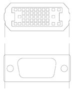
Spent way too much time playing in Illustrator only to come up with not quite to scale art:

HD-45-VGA-002.jpg

Mounting holes for the VGA Connector are a bit closer to the witness lines for mounting tabs which should touch the sides of the connector. There's no way to

Still convinced a simple exterior adapter PCB is the answer, got a couple of new notions for that: KISS! ;)
 
  • Like
Reactions: wottle

Trash80toG4

Active Tinkerer
Apr 1, 2022
953
273
63
Bermuda Triangle, NC USA
External 6100 Adapter has VGA port pointed across the back of the case so Cable is attached for strain relief. (Hot Glue?)
No board or case mods necessary.

RA-STRAIN-RELIEF-HD45-2-VGA.jpg
B.O.M.
PCB
headers (on PCB which insert into HD45)
HD-15 PCB mount, soldertail connector
Double Face Tape (affixes unit to back of case)

Stretch Goal: Nice printed case for the assembly. :D
 
  • Love
  • Wow
Reactions: eric and wottle

Trash80toG4

Active Tinkerer
Apr 1, 2022
953
273
63
Bermuda Triangle, NC USA
Been looking at this design for flaws. Short "throw" of logic board installation is my main concern. It's tight, but probably long enough front to back for careful installation with adapter installed using double sided tape. Velcro might be a better option? How long are the pins on Apple's adapter cable?

Printed case offers some interesting possibilities involving (long throw) strap hinged design with built in strain relief for the cable. Kiss compliant option would be mounting a printed case bottom attached with beaucoups double sided tape for rock solid interface. A boltdown, removable top holding PCB would allow straight vertical removal/installation. Better yet might be firmly attached base with boltdown PCB and snap on or single bolt cover?

7100 has plenty of "throw" for far easier logic board installation and a convenient "lockdown" hole. Only the RA Cable would be blocking fan vents.

6100/7100 machines require model specific PCBs. Don't have an 8100 to examine, anyone got a nice pic of its ass to post?


edit: love the notion of a left angled VGA cable, the OEM adapter cable's wall standoff distance is downright ludicrous. 🙄
 
Last edited:

Trash80toG4

Active Tinkerer
Apr 1, 2022
953
273
63
Bermuda Triangle, NC USA
@wottle I looked at prices on eBay for Apple's cables, OMG! Beginning to thinking this notion for external, no board rework or case mod required kluge might make a viable product for someone here?

License for commercial use available in trade for PCB design of TwinSlot PCI adapters. ;)
 
  • Love
Reactions: wottle

wottle

Active Tinkerer
Oct 30, 2021
576
328
63
47
Fort Mill, SC
@wottle I looked at prices on eBay for Apple's cables, OMG! Beginning to thinking this notion for external, no board rework or case mod required kluge might make a viable product for someone here?

License for commercial use available in trade for PCB design of TwinSlot PCI adapters. ;)
Exactly, imagine trying to get 10 of these for all the machines I just picked up! I've got a PCB coming that might allow for a replacement male connector, and with that, and a 3d printed case for alignment, the wiring to a DB-15 (or likely even better, a VGA connector pre-wired for VGA/SVGA output) would be an ideal solution. It would also likely drive down the costs of the existing HDI-45 adapters. The 3d printed shield would be a challenge, but would be more accessible than my first thought of trying to cut and bend a new metal shield.

I haven't done any 3d printing on metal at JLPCB, but their resin printing is amazing and surprisingly cheap. A 3d printed metal shield that could be mated to a plastic outer casing, all 3d printed and able to be paired up with a couple of PCBs for the male connector and the routing / VGA conversion for the other end... Of course, this all adds complexity.
 

wottle

Active Tinkerer
Oct 30, 2021
576
328
63
47
Fort Mill, SC
External 6100 Adapter has VGA port pointed across the back of the case so Cable is attached for strain relief. (Hot Glue?)
No board or case mods necessary.

View attachment 19399
B.O.M.
PCB
headers (on PCB which insert into HD45)
HD-15 PCB mount, soldertail connector
Double Face Tape (affixes unit to back of case)

Stretch Goal: Nice printed case for the assembly. :D
I think I originally didn't understand this idea, thinking you were proposing mounting a HDI-45 Maile connector, but I understand now - you would simply have header pins mounted at the appropriate locations for the female HDI-45. With long enough headers, this should be relatively easy to accomplish.

I have a set of sample PCBs to see if I could make a PCB that would allow this, the rest would be routing the pins from the HDI to VGA connector, and performing any of the sense line magic needed to get VGA output. A printed one-sided case to keep the pins from being exposed (printed in a nice platinum gray would make for a really nice finished product. And much easier than my plan to try to make a small PCB for the connector, then solder individual wires to the main PCB with the DB-15 connector.

And I think the double sided tape approach for mounting would likely be sturdy enough for most, but what if the PCB had two larger ground holes that you could insert some stronger pieces of metal into that would actually press against 4 sides of the ground shield of the board connector. That would help ensure the pins were aligned on insertion, and hopefully could provide a little more support in keeping the adapter in place.
 

Trash80toG4

Active Tinkerer
Apr 1, 2022
953
273
63
Bermuda Triangle, NC USA
Everything is mounted on the backside of the case. Working up plans for the case currently.

It's a form fitting underlayment/chasssis to be securely double faced taped to the backside of 6100.
PCB will screw down to the base or it'll just slip over pins and be held in place by the top so it cam be removed from Logic board connector.
Top of case holds the PCB connectors in place, maybe just one machine screw connecting it to the base?

I've found 3mm pitch header assemblies, but only shrouded connectors so far. Bare, multilevel header pins needed I think?
 

wottle

Active Tinkerer
Oct 30, 2021
576
328
63
47
Fort Mill, SC
Ah, no, you don't need anything other than some traces and a single diode to adapt from PowerMac video to VGA. The adapters with switches are only needed for older macs, and even they just have like, two diodes in them, unless you're messing with sync and auto detection. Here is the required circuit:

View attachment 19322
What kind of diode would go between pins 7 and 10 to tell the sense lines it should be VGA? And is it really needed here? I actually rigged up a DB-15 to VGA adapter by simply jumping pins 7 and 10.
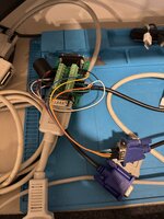
IMG_5063.jpeg IMG_5064.jpeg


So, if I don't need the diode, it's really easy since DB-15 pins 7 and 10 are pins 9 and 18 on the HDI-45 connector, so I can just drop a trace in between there. Here's the board I have that matches the bodge wire version you see above:

Screenshot 2025-01-14 at 11.16.57 PM.png


I still want to think about how I could add something that connect to the HDI-45 shielding to stabilize it and likely make for a better ground connection. I assume I should also connect the ground lines to the grounds on the VGA connector? Also, I don't have any way to attach a 3d printed cover (I don't think we will be able to do a case, since it's already going to be a stretch to get the header pins to reach). So with a single screw that can attach a top cover, the underside of the board will be attached with double sided tape and be "invisible" to the user.

Also, please provide PCB design feedback - I've never done this before, Given the simplicity of the wiring, I was able to to it all on the top of the board. Are there advantages to splitting them up between the top and the bottom of the board? Should I try to add more space between the signal traces to lower the chance of interference? I'm also realizing that I wasted a lot of PCB space horizontally. I can shrink that down now that I got all the trace routing organized. I originally thought I'd have to use vias and add a spot for a diode.

Also, because I'm impatient, I went ahead and ordered a batch of 5 from JLCPCB to see if my measurements and layout are reasonable. For $4, why not?!? Obviously, I will update it with feedback from you all, but I'm actually pretty excited this might work!
 
Last edited:
  • Like
Reactions: Trash80toG4