Need solution for HDI-45 to DB-15 connectors for video out
- Thread starter wottle
- Start date
-
- Tags
- hdi-45 video adapter
-
Please can you read through and vote on the following proposition for changes to the board structure by clicking here.
You are using an out of date browser. It may not display this or other websites correctly.
You should upgrade or use an alternative browser.
You should upgrade or use an alternative browser.
DA-15??? I thought you were doing VGA conversion for HD15 on board? You definitely don't want to see anyone hanging a VGA converter off that thing!I'm test printing the top part of the case that will cover it all except the DA-15 connector
I'm making both. The DOS Compatible card Y cable expects DA-15 input so I can't use a VGA connector (unless I build a VGA to DA-15 adapter). Given it simple enough to make the DA-15 version, this will be for people that have DOS Compatible cards or want to hook up to a vintage Mac CRT.DA-15??? I thought you were doing VGA conversion for HD15 on board? You definitely don't want to see anyone hanging a VGA converter off that thing!
I did this one first simply because it was the board I had opened in Eagle. The shroud was the most complex part, so making another 3d printed case for the VGA version should be quick and simple. I'll even make a version with wings to the side for you to increase the surface area
Here's a video of the full case. It's not quite sitting perfect because it was designed to have a PCB sandwiched in there, but It seems to have good stability. Trying to optimize for low print times and lack of need for supports.
.
As you can see the shroud makes the adapter really stable when plugged in (in addition to ensuring the pins are aligned on insertion). Really excited to get the official PCBs made up and in use in these. My current estimates for these is the following to produce 5:
PCB (JLCPCB): $4.50
19mm 2.0mm pitch headers: $8
3D case (JLC3DP - black resin): $15
Connectors (DA-15 or HD-15): $15
So for 5, the total would be around $45, or $9 each. You can obviously save money if you print the case yourself. But much better than the Apple adapters which are going for ~$40 each. And you can get direct VGA output, so no need for a Mac to VGA adapter. Also, it's lower profile than the Apple adapter, which is bulky and sticks out very far from the back of the machine
Last edited:
Thanks for that explanation, I never understood the DOS Compatible issue you'd been mentioning.I'm making both. The DOS Compatible card Y cable expects DA-15 input so I can't use a VGA connector (unless I build a VGA to DA-15 adapter). Given it simple enough to make the DA-15 version, this will be for people that have DOS Compatible cards or want to hook up to a vintage Mac CRT.
That shroud's amazing, when I first suggested the shroud I was thinking of printing sides of the case and shroud in one piece. making base unit of the case flat on the inside of your case simplifies printing tremendously. Very nice!I did this one first simply because it was the board I had opened in Eagle. The shroud was the most complex part, so making another 3d printed case for the VGA version should be quick and simple. I'll even make a version with wings to the side for you to increase the surface area
My concept was to make the base unit to be attached with double sided tape and the mounting bolt on top of the case. For pulling the mobo the case lid and PCB would be removed. Looks like you have clearance for a third part to be attached permanently to the case with double sided tape. With the mounting screw on top, securing shroud base and lid for removal might be a workable?
Great job and love that video.Here's a video of the full case. It's not quite sitting perfect because it was designed to have a PCB sandwiched in there, but It seems to have good stability. Trying to optimize for low print times and lack of need for supports.
Dynamite! This has turned out so much better than the original concept of bodging connections from the mobo pads of an excised HDI45 connector.As you can see the shroud makes the adapter really stable when plugged in (in addition to ensuring the pins are aligned on insertion). Really excited to get the official PCBs made up and in use in these.
I did this one first simply because it was the board I had opened in Eagle. The shroud was the most complex part, so making another 3d printed case for the VGA version should be quick and simple. I'll even make a version with wings to the side for you to increase the surface area
Here's a video of the full case. It's not quite sitting perfect because it was designed to have a PCB sandwiched in there, but It seems to have good stability. Trying to optimize for low print times and lack of need for supports.
This style of case was pretty much exactly what I imagined when suggesting including the shroud. Great to see it become reality and work this well.
I'm making both. The DOS Compatible card Y cable expects DA-15 input so I can't use a VGA connector (unless I build a VGA to DA-15 adapter). Given it simple enough to make the DA-15 version, this will be for people that have DOS Compatible cards or want to hook up to a vintage Mac CRT.
This is one reason I was interested, as the 6100 DOS compatible is an interesting beast.
I just got lucky this weekend as it turns out my father still had the 7300 with an Orange Micro card in it, and so that will be my next project. A 6100 DOS compatible will have to wait a bit I think.
Where are you located? I have a couple DOS compatible cards and some dirty 6100s that I'm probably going to be selling soon.I just got lucky this weekend as it turns out my father still had the 7300 with an Orange Micro card in it, and so that will be my next project. A 6100 DOS compatible will have to wait a bit I think.
If you've got an ugly one with intact locking tabs and feets I'm only about a 2.5 hour drive from you. It'd be fun to meet up, I've got oodles of trade goods and a little bit of the filthy lucre available.. . . some dirty 6100s that I'm probably going to be selling soon
Where are you located? I have a couple DOS compatible cards and some dirty 6100s that I'm probably going to be selling soon.
Washington state, so about as far away from you as I can get while still being in the lower 48. If the 7300 didn’t drop right into my lap, I would be interested though. For now, I need to see how many of the OrangeMicro 500-series cards still work (I wound up with 3 complete cards), and sort through a bunch of other old Apple things.
Yeah, it's actually coming back closer to my original idea of an adapter. Originally, I was trying to come up with a way to build a 2 PCB adapter (one with just the HDI-45 pins, then a bunch of wires connecting them to the HD-15 or DA-15 connector. That soldering job would have been a nightmare, considering the pin spacing on that HDI-45 connector.Dynamite! This has turned out so much better than the original concept of bodging connections from the mobo pads of an excised HDI45 connector.
When I realized that challenge, I did consider the port replacement idea, thinking it would be easier than the adapter, but the idea of an offset PCB seems like it is the ideal solution.
Also, I just plugged it into the 8100 and I think it will likely work just fine without adjustment.
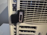
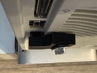
I also just realized I have a 7100 in my massive pile of dirty Macs I picked up in December. It hits the fan fins, but might be able to be in far enough to work as is. However, I will likely make a simple variant of the backs for each machine. The 6100 will be as is, but the 7100 and 8100 will have beveled edges on the parts where they need more clearance. Should be very simply. I mocked on up for the 8100 and will do a test fit. Took me 5 minutes in Tinkercad to make. I also made a countersink area for the screw because it was hitting when the device was plugged into the 8100.
Also, once I confirm the design, I'll print them in the PolyTerra PLA in muted white to match the cases. It's out of stock right now at Amazon, so I'm saving it for important prints.
Last edited:
I definitely have plenty of ugly cases, some with intact tabs. The feet are another story. The guy I bought them from handed me a bag of feet when I picked them up. I've had good luck with the ones with broken tabs using a liberal amount of hot glue inside the feet to keep them in place. Actually keeps them from rattling when moving...If you've got an ugly one with intact locking tabs and feets I'm only about a 2.5 hour drive from you. It'd be fun to meet up, I've got oodles of trade goods and a little bit of the filthy lucre available.
Wonderful! Might I suggest making a pair of holes in the sides where the case overlaps the vent louvers of 7100/8100? When assembling the case you should be able to drop a longish U-shaped wire through them. Bend one wire into a J-shape to fish down thru and then back up in order to twist tie adapter, securing it firmly to the case. Untwist the tie down to pull the shroud out far enough for logic board removal if necessary?
Bevels per machine make a world of sense.However, I will likely make a simple variant of the backs for each machine. The 6100 will be as is, but the 7100 and 8100 will have beveled edges on the parts where they need more clearance. Should be very simply. I mocked on up for the 8100 and will do a test fit. Took me 5 minutes in Tinkercad to make. I also made a countersink area for the screw because it was hitting when the device was plugged into the 8100.
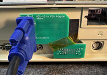
The JLCPBC order of my very early design (no diode, HD-15 right angle connector. One thing I learned and will adjust before the final version is that apparently the HD15 templates in Eagle for the connectors are not universal (rookie mistake). I had to bend the two outer rows outward to fit the holes on my board. But, I soldered up the longer 19mm headers on the HDI-45 side first, then forced the HD-15 connector in place (I actually used one of my straight pinned version because it was easier to get the pins in the right spot).
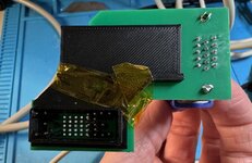
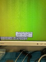
It was one of the very early designs that I hastily ordered on PCBWay because I wanted to verify I could make a working PCB, so it is much wider than the current PCB designs. So I taped one of my current shrouds onto it to help with alignment, plugged it into a 6100, and fired it up:
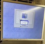
I was a bit surprised because without the diode, I got multiple resolution options:
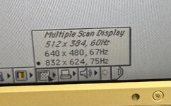
I thought it was going to only give me 640x480. I still plan to add the diode, but this version would likely have been just fine for the 6100s, since I believe they were limited to 832x624 anyway. But maybe for the 7100 / 8100 machines, they can take advantage of the higher resolutions.
So, I confirmed the two things I wanted to with this test:
1. I was able to design a functional PCB and generate the appropriate gerbers to produce a working product
2. I don't notice any issues with the signal quality due to inappropriate grounding or routing of traces.
I will likely try to update my connectors to ensure they match the actual ones I ordered, and get them ordered. I want to get them in hand so I can tweak the fit and placement of my 3d printed cases. Once all done, I will start a new thread with the location of the PCBs, 3d files, and guidance on assembly so people looking to do this won't have to follow my rambling story with multiple design ideas that lead us to finally a good, clean, workable design.
It was one of the very early designs that I hastily ordered on PCBWay because I wanted to verify I could make a working PCB, so it is much wider than the current PCB designs. So I taped one of my current shrouds onto it to help with alignment, plugged it into a 6100, and fired it up:


I was a bit surprised because without the diode, I got multiple resolution options:

I thought it was going to only give me 640x480. I still plan to add the diode, but this version would likely have been just fine for the 6100s, since I believe they were limited to 832x624 anyway. But maybe for the 7100 / 8100 machines, they can take advantage of the higher resolutions.
So, I confirmed the two things I wanted to with this test:
1. I was able to design a functional PCB and generate the appropriate gerbers to produce a working product
2. I don't notice any issues with the signal quality due to inappropriate grounding or routing of traces.
I will likely try to update my connectors to ensure they match the actual ones I ordered, and get them ordered. I want to get them in hand so I can tweak the fit and placement of my 3d printed cases. Once all done, I will start a new thread with the location of the PCBs, 3d files, and guidance on assembly so people looking to do this won't have to follow my rambling story with multiple design ideas that lead us to finally a good, clean, workable design.
I was a bit surprised because without the diode, I got multiple resolution options:
I thought it was going to only give me 640x480. I still plan to add the diode, but this version would likely have been just fine for the 6100s, since I believe they were limited to 832x624 anyway. But maybe for the 7100 / 8100 machines, they can take advantage of the higher resolutions.
Without a diode, the only multi resolution modes available are for VGA and Multiple Scan 13" or 14".
The latter requires a line from sense 2 to sense 1 in place of a diode with ground on sense 0.
If you have just a ground on sense 0, then it's 640x480 67Hz only.
That explains it. I must have misread the post from earlier about the behavior.Without a diode, the only multi resolution modes available are for VGA and Multiple Scan 13" or 14".
The latter requires a line from sense 2 to sense 1 in place of a diode with ground on sense 0.
If you have just a ground on sense 0, then it's 640x480 67Hz only.
OK, I swapped out the part for the HD-15 connector with a footprint for the actual Amphenol part I ordered, adjusted a things, and ordered a batch of both boards. It was relatively cheap to go from 5 to 20 boards, so I will likely have extras, assuming everything goes smoothly with these batches, I can mail them out to others who might want some. Once I confirm the board sizes, I will tweak my cases, and post the full details and instructions on GitHub. Thanks again everyone for helping to iterate through this idea and make it a reality. I hope that this helps bring down the cost of the adapter.
Also, anyone that has experience with how I need to set the licensing of this up so people can use it personally, but not commercially, that would be great.
Also, any need for me to do something like set up an LLC to protect myself if someone uses one of these and shorts some pins and burns their house down?
OK, just returned from a work trip and had a nice little present waiting for me when I got back.
Lots of PCBs!
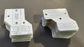
I wanted to make sure the diode worked and the rest of the PCB design was functional, so I soldered the 2.0mm spaced pins, added the diode, then added the HD-15 connector. Used a trial run of my 3d printed backplate with the shroud for alignment (it was a bit off so I had to enlarge the holes), and gave it a test run. Fortunately, it works perfectly, gives me the resolutions I was expecting, and doesn't block anything critical on the 6100. I will have slightly different cases for the 7100 and 8100, but I'm excited to say this version works.
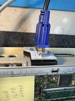
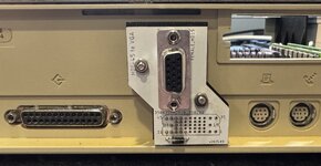
I'm going to solder up one with a DA-15 connector to confirm it will work with my DOS compatibility cards / Y cable. I adjusted my case and am printing a full set (top and bottom) to confirm fit. Once I feel good about it, I will publish the files to GitHub.
A few lessons I learned. First, at least with the white PCBs that I am using, the rings I tried to put around the important pins are impossible to see, so I'll probably make those markings bigger. I also will move those markings to the back side of the board as well, as that is where you will be inserting the pins, so it will be more helpful there. Second, if using the 3d printed case with the pin shroud, you don't need any of the pins on the left side I originally marked as needed, because the shroud handles the alignment, and I originally added those pins to add with proper alignment. So I'll likely remove those from the markings and mention they are optional, really only needed if you aren't using the 3d printed case and are running with a bare PCB.
Lots of PCBs!

I wanted to make sure the diode worked and the rest of the PCB design was functional, so I soldered the 2.0mm spaced pins, added the diode, then added the HD-15 connector. Used a trial run of my 3d printed backplate with the shroud for alignment (it was a bit off so I had to enlarge the holes), and gave it a test run. Fortunately, it works perfectly, gives me the resolutions I was expecting, and doesn't block anything critical on the 6100. I will have slightly different cases for the 7100 and 8100, but I'm excited to say this version works.


I'm going to solder up one with a DA-15 connector to confirm it will work with my DOS compatibility cards / Y cable. I adjusted my case and am printing a full set (top and bottom) to confirm fit. Once I feel good about it, I will publish the files to GitHub.
A few lessons I learned. First, at least with the white PCBs that I am using, the rings I tried to put around the important pins are impossible to see, so I'll probably make those markings bigger. I also will move those markings to the back side of the board as well, as that is where you will be inserting the pins, so it will be more helpful there. Second, if using the 3d printed case with the pin shroud, you don't need any of the pins on the left side I originally marked as needed, because the shroud handles the alignment, and I originally added those pins to add with proper alignment. So I'll likely remove those from the markings and mention they are optional, really only needed if you aren't using the 3d printed case and are running with a bare PCB.
OK, just returned from a work trip and had a nice little present waiting for me when I got back.
Lots of PCBs!
View attachment 20245
I wanted to make sure the diode worked and the rest of the PCB design was functional, so I soldered the 2.0mm spaced pins, added the diode, then added the HD-15 connector. Used a trial run of my 3d printed backplate with the shroud for alignment (it was a bit off so I had to enlarge the holes), and gave it a test run. Fortunately, it works perfectly, gives me the resolutions I was expecting, and doesn't block anything critical on the 6100. I will have slightly different cases for the 7100 and 8100, but I'm excited to say this version works.
View attachment 20246 View attachment 20247 View attachment 20248
I'm going to solder up one with a DA-15 connector to confirm it will work with my DOS compatibility cards / Y cable. I adjusted my case and am printing a full set (top and bottom) to confirm fit. Once I feel good about it, I will publish the files to GitHub.
A few lessons I learned. First, at least with the white PCBs that I am using, the rings I tried to put around the important pins are impossible to see, so I'll probably make those markings bigger. I also will move those markings to the back side of the board as well, as that is where you will be inserting the pins, so it will be more helpful there. Second, if using the 3d printed case with the pin shroud, you don't need any of the pins on the left side I originally marked as needed, because the shroud handles the alignment, and I originally added those pins to add with proper alignment. So I'll likely remove those from the markings and mention they are optional, really only needed if you aren't using the 3d printed case and are running with a bare PCB.
These look like a great product for my web store. Any objection? Wanna work out a deal?
No real objection, other than making sure people that are willing / want to go to the effort to make on their own can still do so.These look like a great product for my web store. Any objection? Wanna work out a deal?
Honestly, you've been so helpful with the Apple /// stuff I've gotten from you, we could probably work out an arrangement, especially if you'd consider maybe trying to get my weird video output issue resolved on it
I just want to make sure if your store stops making them, people in the future could find and make these if needed to get an old x100 machine working.
DM me if you're serious about it and we can discuss.
Printing the HDI-45 to DA-15 case now and the screw holes were slightly off, so trying a second run. Almost to the point where everything is finalized.
OK, printed the cases for the DA-15 and HD-15 versions and still tweaking things to try to ensure the best chance of a solid fit and alignment and to ensure no issues with the insertion / alignment of the pins. But overall they seem to be working great, and are very stable and so I don't think there will be a need for something like double sided tape to provide more stability.
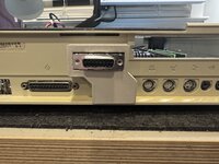
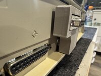
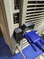
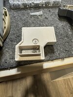
Also, I did print one case with an angled back for the 8100, and the challenges are it gets very thin at one end, and actually results in a hole where the cutout is for the ground attachments are for the HD-15 connector. Also, the screws I use now cannot be countersunk, so they stick out and don't allow it to be as flush as I was thinking. I then tested my 8100 with just the standard 3d printed case and it appears the pins are long enough that it can be pushed in and be usable as is. So I'm leaning towards not having machine specific cases, which may cause more confusion and I don't think provide a ton of value.


Also, I did print one case with an angled back for the 8100, and the challenges are it gets very thin at one end, and actually results in a hole where the cutout is for the ground attachments are for the HD-15 connector. Also, the screws I use now cannot be countersunk, so they stick out and don't allow it to be as flush as I was thinking. I then tested my 8100 with just the standard 3d printed case and it appears the pins are long enough that it can be pushed in and be usable as is. So I'm leaning towards not having machine specific cases, which may cause more confusion and I don't think provide a ton of value.
