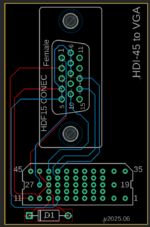
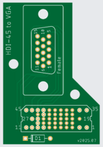
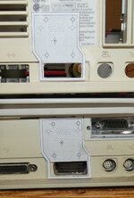
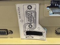
Need solution for HDI-45 to DB-15 connectors for video out

Trash80toG4

Active Tinkerer
Apr 1, 2022
997
291
63
Bermuda Triangle, NC USA
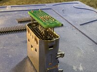
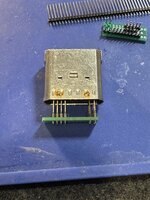
Installation of headers should be a snap when the connector can be used as an assembly jig.
Yeah, that diagram was for the PCB pins on the board, not the external connector. The connector is actually less than 2mm between pins.
That's what I was thinking in scaling the graphic, only the horizontal spacing would be a given?

I just did that real quick. The pins on the adapter appear to be ~0.6mm round pins. The pins I used were 0.5 square pins.
Then we should be looking into machine pin headers with their round pins I'd think?
 
Last edited:

wottle

Active Tinkerer
Oct 30, 2021
645
389
63
47
Fort Mill, SC
Installation of headers should be a snap when the connector can be used as an assembly jig.

That's what I was thinking in scaling the graphic, only the horizontal spacing would be a given?


Then we should be looking into machine pin headers with their round pins I'd think?
Yes, I have some 0.52 round header pins on the way, but couldn’t find any 2mm pitch longer headers (probably will need ~12mm length) with round pins.

This was just to test the spacing of my HDI-45 layout in Eagle. Although I did confirm all the pins fit very snug and were making secure contact, so if someone doesn’t want to go through the expense and hassle of individual pins for all ~20 or so pins, the square pins in a traditional header would likely work great.

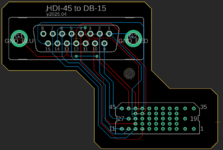
FYI, here's the DB15 version of the board:

Screenshot 2025-01-17 at 5.33.47 PM.png

The routing was a bit more complex (the VGA pins were so simply it allowed me to do it all in on layer, this one unless I missed a routing opportunity, required two layers and a couple of vias to get everything connected properly.
 
Last edited:
  • Like
Reactions: eric

Trash80toG4

Active Tinkerer
Apr 1, 2022
997
291
63
Bermuda Triangle, NC USA
Great stuff, but why do you have such a large horizontal offset between connectors? Such a wide spread works well enough on the 6100, but not at all on the 7100, where the cooling vents preclude such an arrangement?

The slight offset to the left in my proposed layout clears the PDS expansion slot of the 6100, but stops short of running into the 7100 cooling exhaust louvers. ;)
 

wottle

Active Tinkerer
Oct 30, 2021
645
389
63
47
Fort Mill, SC
Great stuff, but why do you have such a large horizontal offset between connectors? Such a wide spread works well enough on the 6100, but not at all on the 7100, where the cooling vents preclude such an arrangement?

The slight offset to the left in my proposed layout clears the PDS expansion slot of the 6100, but stops short of running into the 7100 cooling exhaust louvers. ;)
I was trying to avoid interfering with the PDS slot screws. And giving more space for the potential 3d printed cover. I also don't have a 7100 to see where the cooling vents are. Looking at my 6100, it does appear I could put it closer to the right. I'll adjust my PCB...
 

Trash80toG4

Active Tinkerer
Apr 1, 2022
997
291
63
Bermuda Triangle, NC USA
Just re-read my post, seems kinda blunt, no criticism intended. I've got both cases handy, but haven't printed it out for fitment. I'll post a .pdf you can print out for reference, including an outline of the space available for both cases.

Offset should be plenty for PDS. May be a bit too much for the 7100.
Haven't put a ruler on them yet, going by eye, which is usually pretty accurate, but we'll see. :)


edit: no time for rulers or AI playtime before work, but this should give you an approximation for today.

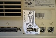
P1000730.JPG


HD45-to-VGA-offset-00.jpg
 
Last edited:

wottle

Active Tinkerer
Oct 30, 2021
645
389
63
47
Fort Mill, SC
Just re-read my post, seems kinda blunt, no criticism intended. I've got both cases handy, but haven't printed it out for fitment. I'll post a .pdf you can print out for reference, including an outline of the space available for both cases.

Offset should be plenty for PDS. May be a bit too much for the 7100.
Haven't put a ruler on them yet, going by eye, which is usually pretty accurate, but we'll see. :)


edit: no time for rulers or AI playtime before work, but this should give you an approximation for today.

View attachment 19529

View attachment 19530

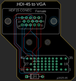
If you have the chance, can you get a measurement from the farthest left pins of the HDI-45 connector, to where the fan fin bump outs start? My current VGA design extends 14mm left of the leftmost pins. Wondering if the will be enough. The other option that might alleviate the need for all of this, although it would look weird, would be to align the VGA connector vertically. Seems like we have more space. With that, I suspect I could make the board a rectangle.

1737239231174.png


Something like this:

Screenshot 2025-01-18 at 5.45.29 PM.png


It would fit vertically in the space of the 6100 and 7100. It's going to impose a. bit on the fan bump out of the 8100, but I'm guessing many 8100 owners have video cards (this may be a bad assumption). But even on the 8100, this is workable as long as the pins for the HDI-45 connector are long enough that it can be set out from the machine a bit more.

This vertical orientation won't work for my DB-15 version, but that one is mostly to accommodate the 6100 DOS Compatible's need for a DB-15 connection. Since the 7100, that I'm aware of, was never offered with the DOS card, that potential audience is much smaller.

So I'm thinking the vertical orientation of the HD-15 connector, and then the wider, offset version for the DB-15 converter.
 
Last edited:

Trash80toG4

Active Tinkerer
Apr 1, 2022
997
291
63
Bermuda Triangle, NC USA
I'll see what I can do after work tonight. We're talking about three connectors, HDI45, HD-15 and DA-15, DB only refers to the form factor of the BB-25 shell. HD-15 is three rows of pins the the 9-pin DE-9 shell. Pickin' nits here, but technically correct terminology helps much when working as a team. ;)


edit: forgot, minimal jag to the left necessary to clear PDS hardware for 6100. Rectangular unit won't work.
 
Last edited:

wottle

Active Tinkerer
Oct 30, 2021
645
389
63
47
Fort Mill, SC
I'll see what I can do after work tonight. We're talking about three connectors, HDI45, HD-15 and DA-15, DB only refers to the form factor of the BB-25 shell. HD-15 is three rows of pins the the 9-pin DE-9 shell. Pickin' nits here, but technically correct terminology helps much when working as a team. ;)
Appreciate the clarification. I always have used DB-15 vs DA-15 as what I thought was a technically incorrect but accepted usage. Good luck finding a DA-15 cable searching google. But I will be sure to use the proper connector identifier from here on out.

edit: forgot, minimal jag to the left necessary to clear PDS hardware for 6100. Rectangular unit won't work.

Ah, you are correct. I need to narrow it but may have enough room to make it more of an arrow shape.Or maybe just notch one side. Want to leave enough room for the double sided tape to give good hold.
 

wottle

Active Tinkerer
Oct 30, 2021
645
389
63
47
Fort Mill, SC
Decided to only notch in the one side, as it gives more room for double sided tape, and also gives me enough bare PCB to punch another hole for mounting the case. Also added some white circles around the minimum pins that need to be connected to have it work and not allow for plugging in wrong.

Screenshot 2025-01-18 at 9.36.20 PM.png

Although I did find that the spacing does allow me to plug it in shifted to the right by one pin. Trying to keep it relatively simple as I'm hoping this is one that can be plugged in once and left in most of the time. The good news is because the ADB pins are not connected, so shifting right would still not risk shorting the 5v ADB line, even if you shorted the pins while soldering them in. I think the worst that would happen if you plugged this in shifted to the right is you'd get no video out, which would be your sign to pull the board and shift it to the left a bit.
 

Trash80toG4

Active Tinkerer
Apr 1, 2022
997
291
63
Bermuda Triangle, NC USA
Thanks for agreeing to technical, if not common use terms. This is, after all, at least a half assed engineering endeavor. :ROFLMAO:

Initial insertion has to be spot-on as that's when the D/F tape of the case is set. PCB will need to be held tightly, keyed exactly in place sandwiched between the top/bottom of the case.

Adapter PCB will need to be removed before removal of the Logic Board of the 6100. There's not enough "throw" front to back for the adapter's pins co clear the connector upon removal and bending them is not good.

"Throw" front to back in the 7100 appears to be sufficient, but there's still too much side to side play when installing the logic board as far as I'm concerned. Check it out on your 6100, front to back motion in sliding out the logic board appears to be slightly less than the pins interfacing the HDI45?

I remain wedded to my illustration, your vertical design seems not to have enough surface available on the backside for firmly securing it. Remember, both cases step up just above the HDI45 port. I think we need to make the Case/PCB as wide above the HDI45 as possible in support of both machines for employing beaucoups D/F tape to the case/adapter interface. Not sure going with a vertical connector is a good idea there. ;)

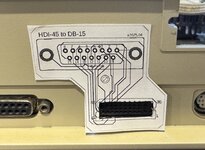
HD45-to-VGA-013.jpg
 

Trash80toG4

Active Tinkerer
Apr 1, 2022
997
291
63
Bermuda Triangle, NC USA
Too tired to take a better pic tonight, but this'll do for now:

HDI45-to-VGA-00.JPG

Time to buckle down and take off some real measurements for the next version, here's the .pdf for printout as it stands:
 

Attachments

  • HDI45-to-VGA-012.PDF
    109.5 KB · Views: 32

wottle

Active Tinkerer
Oct 30, 2021
645
389
63
47
Fort Mill, SC
Too tired to take a better pic tonight, but this'll do for now:

View attachment 19632

Time to buckle down and take off some real measurements for the next version, here's the .pdf for printout as it stands:
It looks like in the 6100 picture that the bottom section by the HDI-45 port is not centered on the connector. If you center it, it looks like it will overlap, or be very close to the screw hole that I need to use for securing the DOS car adapter bracket. With the hope of 3d printing a case, it feels like it would not provide sufficient clearance to have the 3d printed case around it.

I'm going to see if I can print a mock-up of the vertical mounted connector and see how it looks. Any concerns about surface area for the tape could easily be addressed with the 3d printed case.

Appreciate all the brainstorming here!
 

wottle

Active Tinkerer
Oct 30, 2021
645
389
63
47
Fort Mill, SC
Too tired to take a better pic tonight, but this'll do for now:

View attachment 19632

Time to buckle down and take off some real measurements for the next version, here's the .pdf for printout as it stands:
It looks like in the 6100 picture that the bottom section by the HDI-45 port is not centered on the connector. If you center it, it looks like it will overlap, or be very close to the screw hole that I need to use for securing the DOS car adapter bracket. With the hope of 3d printing a case, it feels like it would not provide sufficient clearance to have the 3d printed case around it.

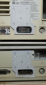
Here's the vertical oriented board I got against my 6100. I feel like any concerns over surface area could easily be addressed with the 3d printed case. If you want more, there can be a case specific to the machine to provide maximum surface ares for the area allowed. I also took a picture with a rough location on the Quadra 650, which is very similar to the 7100.

IMG_7730.jpeg IMG_7732.jpeg

And here is the version I need to my DOS Compatibles. Obviously the wider DA-15 (formerly known as DB-15 in my posts) is going to overlap the fan fins, but the vertical one fits nicely, as expected. Since the DA-15 version is primarily for the DOS Combatible Y cable needs, and that is primarily used in the 6100, I'm not too concerned about that. Also, I don't see a good alternative other than a machine specific version (wouldn't be hard to do, but I'll leave that to some future 7100 DOS Compatible owner to decide if it is worth it).

IMG_7733.jpeg IMG_7734.jpeg

Appreciate all the brainstorming here!
 

Trash80toG4

Active Tinkerer
Apr 1, 2022
997
291
63
Bermuda Triangle, NC USA
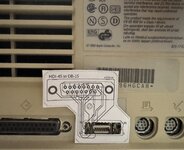
Like I said, that version was measured mostly with Mk.1 eyeball. Here's the updated version ready for printout testing.

HDI45-to-VGA-020.jpg


Clearances should be appropriate. I'll whip up a 3D model to test clearance for the PDS bracket knob. My main concern with your vertical card would be lack of sufficient surface area for firmly securing the adapter with D/S tape?
 
Last edited:

wottle

Active Tinkerer
Oct 30, 2021
645
389
63
47
Fort Mill, SC
My main concern with your vertical card would be lack of sufficient surface area for firmly securing the adapter with D/S tape?
As I said, I think any concern here would be addressed with the case. It’s much easier to build multiple 3d printed options to increase / optimize surface areas for adherence to the case. Obviously, I’m not going to stop you from designing one with a horizontal connector, I just think there will be challenges with trying to be so precise with the fit, especially since you’d need to make special conditions on the case to ensure they don’t cause fit issues if the PCB is using all the space. Options are certainly great for everyone, so I am by no means saying my vertical option is the only solution.
 

Trash80toG4

Active Tinkerer
Apr 1, 2022
997
291
63
Bermuda Triangle, NC USA
Didn't take it that way at all, not saying my way is the only approach either. ;)

My (unvoiced?) concern has been re-alignment of the adapter PCB when re-installed after having been removed for pulling the logic board. The support pin/stud spread at the four corners help to ensure alignment and prevent axial stress on the pins.

The indicated centered bolt secures the lid. Socketed studs of lid hold the PCB firmly in place on the pins of the support studs in a tight sandwich. Widening your board just enough to splay support/alignment points out in such manner would prove effective for same.

Vertical orientation of the connector is a great idea, creating a wide margin of error for 6100/7100 case compatibility and improved access to the PDS Card cage mounting stud of the 6100.

I'm just happy to have helped in getting the solution out the logic board modification realm, up and outside case for a complication free arrangement. Have at it! :)
 
  • Like
Reactions: wottle

wottle

Active Tinkerer
Oct 30, 2021
645
389
63
47
Fort Mill, SC
OK, I got my longer 2mm pitch header pins, as well as some round machine pin headers. The machine pin headers are a bit shorter, at about 11mm total length. The square pin headers are 19mm total length.

I wasn't sure if the machine pin headers would be a good fit, because the closest diameter I could get for that would be small enough to fit the holes on the pcb was 0.02in (0.51mm). The original pins on the HDI-45 male connector was closer to .6mm. So I wanted to take two of my test PCBs and use both type of connectors and see which one fit better. The machine pin headers weren't terribly cheap, so I only fit the minimum to get it to seat properly.

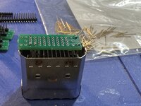
Here's the regular square 2mm pitch headers:
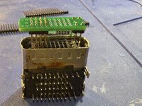
IMG_9720.jpeg IMG_9721.jpeg IMG_9722.jpeg

As you can see, there's plenty of room for clearing the case, as well as any 3d printed backing, and the double sided tape. May not even need to trim any of the pins down. The fit is very secure, and the addition far pins make it much harder to plug in wrong (not impossible, although without a shroud on the back side, the longer pins are going to make it hard to prevent incorrect plugging in.

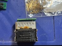
Here are the shorter 11mm machine pins. I think they will be too short to be usable. I'll have to see if I can find some with the same diameter, but with a longer total length. Unfortinately, the next size up of the ones I used are 26mm in length, and are $0.30 each. That will get costly since there should be 20 pins on each connector. The pins alone will add $7 to the cost of the adapter.
IMG_9723.jpeg IMG_9724.jpeg

The fit is looser than the square pins. It could partially be due to the fact I only installed 4 pins. However, installing individual pins is tedious and much more time consuming than the headers that come with spacers. Even using the existing connector as a jig to align the pins, it is tough because the longer pins mean moving each individual pin to get them to slide into the PCB holes.

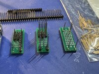
Here's the various test PCBs with standard length header, 19mm square headers, and 11mm machine pin headers:
IMG_9725.jpeg

Given the looser fit, the more challenging installation, and the higher cost, I think the square pins are the right choice for me. With the longer pins, I actually am beginning to think this may allow this to even work on the 8100. We'll see when my larger PCB comes in and I can do a quick test.

I'm hoping my test PCB with the earlier design (90 degree VGA connector going to the left, no diode, so 640x480 on this board). However, I was mainly wanting to see if my sizing would work, and the pins would be long enough for the larger PCB.

I've got some idea for a 4d printed case that I may start typing with, so more to come on that front...
 

Trash80toG4

Active Tinkerer
Apr 1, 2022
997
291
63
Bermuda Triangle, NC USA
As you can see, there's plenty of room for clearing the case, as well as any 3d printed backing, and the double sided tape. May not even need to trim any of the pins down.
Very cool! Trimming pins on the insertion side would be a no-no. I've clamped the pins in a vise and tamped the plastic spacers down to length. Given the thickness of the printed case, trimming them on the solder side shouldn't be necessary.

Again, fantastic work! ;)


edit: thinking about it, making a jig to hold the assembly and clamping the jig down in the Vise would nicely achieve custom length pins.
 
  • Love
Reactions: wottle

wottle

Active Tinkerer
Oct 30, 2021
645
389
63
47
Fort Mill, SC
Very cool! Trimming pins on the insertion side would be a no-no. I've clamped the pins in a vise and tamped the plastic spacers down to length. Given the thickness of the printed case, trimming them on the solder side shouldn't be necessary.

Again, fantastic work! ;)


edit: thinking about it, making a jig to hold the assembly and clamping the jig down in the Vise would nicely achieve custom length pins.

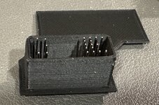
As I've been testing my 3d printing design skills and test fitting some pieces, I'm starting to think that the 19mm pins may be perfect. With the shroud I printed, I think it will sit just right with the pins, and I will likely extend the area behind the DA-15 / HD-15 connector to provide just the right clearance for double sided tape. But with the plastic, 3d printed shroud, the pins should be perfectly aligned and make for easy insertion and removal. The sketch tool in Tinkercad is pretty awesome for this simple type of work.

Here's a look at a test print of the bottom.

IMG_0385.jpeg

For ease of printing, this will be flat, with the shroud coming out one side (as well as maybe a thicker body to accommodate the length of the pins to site near flush to the casing). With that thicker casing, I might even be able to sculpt it out a bit to work on the 8100! Then the top of the case will have the sides, and the cutout for the appropriate connector, with hopefully a single screw post for the hole on the bottom piece and PCB. The 3 components will sandwich together held by the single center screw, and the case should fit snug around the PCB to keep it all in the right spots.

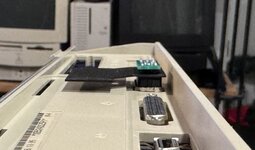
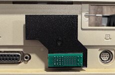
Here is it in the back of a 6100:

IMG_0382.jpeg IMG_0384.jpeg


I'm test printing the top part of the case that will cover it all except the DA-15 connector, and hopefully it will verify that my approach will work. Then, assuming the test PCB I have coming this week works, I will order the official boards and confirm they fit, all the openings are in the right place, etc. Fortunately, as long as the PCB has no flaws, any adjustments should be just to the 3d model.
 
  • Like
Reactions: eric