"Spicy O'clock" project has started

Kay K.M.Mods

Active Tinkerer
Sep 23, 2021
296
653
93
Tokyo
www.kerosmm.com
OK, so I need to try that, I had seen the video from @JDW about it.
And also watch the quality of the PSU caps. They all "looked" fine with no leaks, but this does not mean they are still at their nominal values.

I know partially put the Mac back in the case so I could plug the HD more easily. Please do not blame me if it doesn't look right yet !
You can see a successful boot @ 30 MHz with ADB plugged in, so quite ok. It did freeze a few minutes after boot, but keep in mind it's currently a test bench, and when the case is opened there is no airflow.
View attachment 7269
View attachment 7268
I also took a picture of the clock signal out of the Spicy. I'm surprised as it looked cleaner with no load, ie was a very nice sinusoid. Is that kind of waveform expected ?

View attachment 7270
A sine wave is different from a jagged waveform like a crystal oscillator.

Even so, it becomes slightly unstable around 30MHz, which is the upper limit of this variable oscillator used for Spicy. However, since it is designed exclusively for the 68040, the upper limit of Spicy itself is 26MHz (CPU 52MHz), so there are no bad effects.

And a lot of people overlook it, but Spicy's trimmer pot can be operated while the Mac is running. This is because the correct sine wave is output so that the silicon oscillator is not affected even if the trimmer is slightly changed.
 
  • Like
Reactions: iPhil64

iPhil64

Tinkerer
Apr 5, 2022
122
86
28
France
A sine wave is different from a jagged waveform like a crystal oscillator.

Even so, it becomes slightly unstable around 30MHz, which is the upper limit of this variable oscillator used for Spicy. However, since it is designed exclusively for the 68040, the upper limit of Spicy itself is 26MHz (CPU 52MHz), so there are no bad effects.

And a lot of people overlook it, but Spicy's trimmer pot can be operated while the Mac is running. This is because the correct sine wave is output so that the silicon oscillator is not affected even if the trimmer is slightly changed.
Thanks for the info ! We do learn so much.

In my case, I DID realise I could change the trimmer on the fly :) I used it a lot to try and guess the upper limit that I could reach.
Spicy is a fantastic tool. I have started with my 660AV, but I have other machines to play with, just need more time !

The good news in the end is that even if some clocks are derived from the same divider as the CPU, there is some room for overclocking.
Now, I will explore which other part is causing instabilities. As the CPU is currently under clocked, we know it's nit the culprit.
 
  • Like
Reactions: Kay K.M.Mods

JDW

Administrator
Staff member
Founder
Sep 2, 2021
1,580
1,377
113
53
Japan
youtube.com
PPC card and Spicy O'Clock!
I just finished watching. Very nice video.

I wrote a comment under the video to explain that the LC575 board is very sensitive when it comes to overclocking. I'm curious if he tried stably overclocking beyond 45MHz (a) with the PPC card completely removed, or (b) with a different 040 CPU.

I of course didn't have a PPC card in my testing, but once recapped with OS-CON caps and with a 40MHz rated 040 processor, I was able to achieve a stable 49MHz with Mr. Fahrenheit's 60ns VRAM (PCB by Stephen Arsenault) and 50MHz with the 2-chip SMC VRAM. So it could be either the CPU and/or the presence of the PPC upgrade card that is the limiting factor for overclocking the 040. Not that it matters in his case though because once the PPC card is installed, it seems to be the limiting factor at about 85MHz.

Hopefully, the video by Action Retro inspires many other people to give Spicy O'Clock a try on their 040 Macs! It's really a great product, and I'm somewhat surprised the vintage Mac world isn't ablaze with raves about it. It really needs to get a lot more press coverage. It's a ground-breaking upgrade, to be sure.
 

retr01

Senior Tinkerer
Jun 6, 2022
2,473
1
796
113
Utah, USA
retr01.com
Hopefully, the video by Action Retro inspires many other people to give Spicy O'Clock a try on their 040 Macs! It's really a great product, and I'm somewhat surprised the vintage Mac world isn't ablaze with raves about it. It really needs to get a lot more press coverage. It's a ground-breaking upgrade, to be sure.

I agree. I have not seen anything like that. Great stuff to spice up the 040 Mac! :) Way to go, @Kay K.M.Mods! :D(y)

giphy.gif
 
  • Haha
Reactions: Kay K.M.Mods

Kay K.M.Mods

Active Tinkerer
Sep 23, 2021
296
653
93
Tokyo
www.kerosmm.com
I just finished watch. Very nice video.

I wrote a comment under the video to explain that the LC575 board is very sensitive when it comes to overclocking. I'm curious if he tried stably overclocking beyond 45MHz (a) with the PPC card completely removed, or (b) with a different 040 CPU.

I of course didn't have a PPC card in my testing, but once recapped with OS-CON caps and with a 40MHz rated 040 processor, I was able to achieve a stable 49MHz with Mr. Fahrenheit's 60ns VRAM (PCB by Stephen Arsenault) and 50MHz with the 2-chip SMC VRAM. So it could be either the CPU and/or the presence of the PPC upgrade card that is the limiting factor for overclocking the 040. Not that it matters in his case though because once the PPC card is installed, it seems to be the limiting factor at about 85MHz.

Hopefully, the video by Action Retro inspires many other people to give Spicy O'Clock a try on their 040 Macs! It's really a great product, and I'm somewhat surprised the vintage Mac world isn't ablaze with raves about it. It really needs to get a lot more press coverage. It's a ground-breaking upgrade, to be sure.
Thanks James!

In his video, I could feel his respect for me and @JDW and @Stephen .

Of course, you who are YouTubers are always aware that the contents of your videos are independent and original. So you should always strive to be exciting in order to surprise others, you could do it too
I definitely think it's great that he approached with PPC cards. I sent him technical advice on that. I think he can develop it in time!

You and him have different approaches, so I can't compare them, but I can say that both are great.
My device isn't very useful 🤣, but it's small, cheap, and designed so that anyone can come up with ideas.It doesn't require a lot of programs and I like simple things.
 
  • Love
Reactions: Stephen

JDW

Administrator
Staff member
Founder
Sep 2, 2021
1,580
1,377
113
53
Japan
youtube.com
Yeah want it be better than tape.

Forgot to mention that when installing I would recommend slipping it on one edge first and then use a screw driver the bend the clip outward a bit on the opposite edge while pushing down . This will help prevent damage to lip on the clip that holds onto the edge of the 68040. Same procedure in reverse to remove the clip.
@alxlab
What's the best way to buy one of your heatsink clips, for people totally brain-dead to 3D printing? :)

1665121989687.png


By the way, I found this 45mm heatsink on Mouser that spans the whole width of the 68040, but sadly it is a whopping 22mm tall, which means you cannot put a 40x10mm fan on top, and there's no room to put the 40mm fan on the side either. Even if there was a custom clip that allowed use of Thermal Grizzly Kryonaut*, I'm unsure if it would offer better cooling as a purely passive heatsink than the existing 45x10mm gold aluminum heatsink* + Noctua 40mmx10mm fan* combo I'm using now.

I see you also mentioned the pure copper 40x10mm heatsink on AliExpress. I don't see a way for a custom 3D printed clip to hold that down, which means you'd need to use thermal tape with it, and we of course know thermal tape doesn't transfer heat well, which is why you created that 3D clip-mount for the gold 45mm heatsink.

The only other thing I can add is that the Thermal Grizzly Carbon Pad* seems to offer thermal conductivity on par with Kryonaut, which is pretty incredible. The downside seems to be that the pad can tear easily, especially if the heatsink is removed. Some users of the pad have said it should be a single use pad. But the upside to the pad is that you would never need to change it, unlike thermal paste. The pad's 51x68mm size would need to be cut down to 45x45 with scissors, and then one of your heatsink clips would need to be used with the gold 45x45x10mm heatsink. Your heatsink clip would need to pull the heatsink down quite firmly and flat onto the CPU though, because the pad is only 0.2mm thick. That important detail is pointed out at 17:20 in this video review. The 40mm Noctua fan could then be mounted on top using two bolts as shown in my video here.

The ultimate aim here is to achieve the best cooling possible within the space constraints of each Mac. In my case, that is a Color Classic, which means the total height of a heatsink + fan stack cannot be much more than 20mm. Even now, my floppy drive ribbon cable almost touches the top of the fan.

One thing I found in August (the hottest month of the year in Japan), is that I was getting screen artifacts that I didn't get in the cooler months of the year (when running at 50MHz). True, I added an Apple IIe Card in August which I didn't have earlier in the year, so maybe that is heating things up inside. The artifacts got so bad I had to drop the clock speed down to 49.0MHz. Those are the same pixel artifacts shown in my Spicy videos, when the clock speed is too high. I had previously thought it was the slowness of the 60ns VRAM, but now I believe that the actual temperature of the CPU may be a part of the problem too.

This is why I asked how to buy your heatsink clip so I could experiment with Thermal Grizzly Kryonaut and possibly that carbon pad too. Without the heatsink clip, those ways to improve thermal conductivity cannot be used. The effectiveness of the fan atop my heatsink is limited by the thermal conductivity of the 2-sided tape* I use now between the the CPU & heatsink. I have no idea the specs of my tape, but a similar MADE IN CHINA tape here* claims 1.5 W/M-K. The Carbon pad claims 62.5 W/mk. That's an enormous difference!

* affiliate links
 

retr01

Senior Tinkerer
Jun 6, 2022
2,473
1
796
113
Utah, USA
retr01.com
Thank you, @JDW, for bringing this up! I am considering getting Spicy Clock, and this solution by @alxlab would be fantastic. I look forward to printing that on my 3D printer. I agree that there should be someone who can print for someone. :)
 
  • Like
Reactions: JDW

alxlab

Active Tinkerer
Sep 23, 2021
287
312
63
www.alxlab.com
With regards to where to get the heatsink clip I'm always willing to sell the designs I've made by just PMing me either on this forum or on the Tinker Different discord. My initial thought would be to sell just the clip for $5 USD and a clip with the heatsink for $10 USD. At some point I'll have a store setup on my website to make it easier.

Regarding the 40mm copper heatsink, a 3D printed clip should be doable. It's just a matter of buying one and getting the dimensions of the clip right. I actually just asked the seller if they could make a 45x45x10mm version of the heatsink.
 
  • Love
  • Like
Reactions: JDW and retr01

JDW

Administrator
Staff member
Founder
Sep 2, 2021
1,580
1,377
113
53
Japan
youtube.com
With regards to where to get the heatsink clip I'm always willing to sell the designs I've made by just PMing me either on this forum or on the Tinker Different discord.
Perfect. Thank you very much for that information!

I actually just asked the seller if they could make a 45x45x10mm version of the heatsink.
I actually thought about asking them to do that too because they are based in China and have that ability, but thank you for taking that proactive step. Pure copper will offer definite cooling benefits over aluminum, and a 45mm width with a 10mm height is just right for the 68040 processor in pretty much any application, especially the tight spacing constraints of a Color Classic.

One thing I am very curious about in all of this discussion centers on "torque" as described here:

Regarding your heatsink clip, I am curious how hard the clip forces the heatsink to press down on the CPU. Perhaps there is no way to quantify that pressure ("torque"), but after watching that YouTube video, I can see that the "torque" directly corresponds to the heat transfer performance of either a carbon pad or thermal paste. If there isn't enough pressure, especially if you use a carbon pad instead of paste, there will be very poor thermal conductivity.

But let's say your heatsink clips press the heatsink down onto the CPU at a near ideal amount of pressure. Because the clips are made of melted plastic (which is what 3D printers do), and because they are in constant contact with a high heat source (the CPU edges and the heatsink itself), would that 3D printed plastic weaken/loosen over time such that the "torque" would become less?

Maybe this is something we cannot know (outside testing the clip for a few years), but it is something I've been pondering in this discussion. The benefit of using a carbon pad over thermal paste is that you wouldn't need to swap out the pad ever again. But if the heatsink clip weakens over time, then it would be the achilles heel in what we are trying to achieve.
 

Drake

TinkerDifferent Board Vice-President 2023
Staff member
Sep 23, 2021
447
782
93
With regards to where to get the heatsink clip I'm always willing to sell the designs I've made by just PMing me either on this forum or on the Tinker Different discord. My initial thought would be to sell just the clip for $5 USD and a clip with the heatsink for $10 USD. At some point I'll have a store setup on my website to make it easier.

Regarding the 40mm copper heatsink, a 3D printed clip should be doable. It's just a matter of buying one and getting the dimensions of the clip right. I actually just asked the seller if they could make a 45x45x10mm version of the heatsink.
haha, too smart! hopefully they're able to accommodate that size easily.
 

iPhil64

Tinkerer
Apr 5, 2022
122
86
28
France
Hi all... back after a long time.
I started replacing my tantalum caps by OS-CON on my 660AV motherboard.

Except I was not cautious enough, and broke a leg of the MC88920... bummer. :( It's really broken close to the package and of course, this is pin 8...

UTSource lists some variants as new old stock, namely 88920DW, DWR, DWR2, or MC88920 as inquiry (though their data sheet is MC88921...

I have started to look for data sheets for comparison, and there are some variations. Any advice/recommandation ? Maybe @Kay K.M.Mods ?
IMG_0122.jpegIMG_0121.jpeg
 

Drake

TinkerDifferent Board Vice-President 2023
Staff member
Sep 23, 2021
447
782
93
Hi all... back after a long time.
I started replacing my tantalum caps by OS-CON on my 660AV motherboard.

Except I was not cautious enough, and broke a leg of the MC88920... bummer. :( It's really broken close to the package and of course, this is pin 8...

UTSource lists some variants as new old stock, namely 88920DW, DWR, DWR2, or MC88920 as inquiry (though their data sheet is MC88921...

I have started to look for data sheets for comparison, and there are some variations. Any advice/recommandation ? Maybe @Kay K.M.Mods ?
View attachment 9586View attachment 9585
Without looking at replacements I can say with confidence that you can still recover that leg.
It's worth a try especially if you're considering replacing (what's to lose).
If you have a scalpel shave away some of the epoxy, better yet a fine point Dremel.
 

iPhil64

Tinkerer
Apr 5, 2022
122
86
28
France
Without looking at replacements I can say with confidence that you can still recover that leg.
It's worth a try especially if you're considering replacing (what's to lose).
If you have a scalpel shave away some of the epoxy, better yet a fine point Dremel.
You are right, no harm in trying :)

Will finish recapping with OS-CON first, just in case I'm stupid again !
 
  • Like
Reactions: JDW

iPhil64

Tinkerer
Apr 5, 2022
122
86
28
France
So ! I think it will work. thank you for the suggestion @Drake !

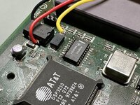
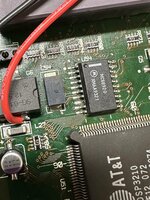
This is how it looks like before a bit of cleaning. I will also put some hot glue to secure the yellow wire, as the solder point on the IC is extremely tiny ! I even wonder how I made it. Scraping the epoxy around what was left of the pin was not so easy (I don't have a small enough dreamed, so did it with the scalpel), and it took me at least 10 tries.

Also I reversed all wires so they would flow together in the same direction, and I can relocate the spicy more easily. Far better option than what I had done initially.

Hopefully I can test later.

Capture d’écran 2022-11-02 à 16.52.45.png