Hello everyone,
Just before the New Year, I received the components necessary for upgrading the lens on my Type C system. Since then, I've finished all of the physical upgrades, and thought everyone might find my process informative. My first approach was to utilize the part files 0dan0 had graciously provided, but as I progressed, I decided to design my own parts. I've got FDM and MSLA part printing capabilities at home, so iterating the designs was relatively simple and they did the job I needed.
At the end, I've put together a comparison image attempting to show the detail improvements I see with all of the physical upgrades. I hadn't seen this type of comparison before, and I found it helpful to qualify the investment I've put into this humble consumer scanner. I hope that it helps answer questions about whether or not upgrading the lens is worth it (I'm convinced!). Note however that I've only been using V6.6 firmware up to this point and that's reflected in the comparison image. I'm looking forward to trying the newest FW versions in the coming weeks!
Hardware Upgrade Process
Accessing the lens and image board- I've seen stills from others, but I thought a quick video would be helpful.
View attachment 25962
Removing stock lens- The adhesive fixing the focus on the original lens and preventing its removal appears to be a type of hot glue stick. Applying some heat (high heat not necessary) for about a minute softened it enough to pull off with pliers.
View attachment 25963
View attachment 25964
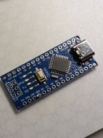
Removing the image board- Remove the four outermost screws. I measured the screws holding the board to the system and concluded mine are M1.7. Probably self threading. An unusual size. I stuck with M1.7's for better or worse. You might get away with slightly larger screws if they're easier to procure.
View attachment 25965
View attachment 25966
View attachment 25967
Removing the image board from the ribbon cable- I used a spudger to rotate the black retention feature up. The cable then easily slips out. Be careful lifting the retention feature, it's fragile and not meant for repeated actuations
.
View attachment 25968
View attachment 25969
Removing enclosure material above the image board- The new lens will need to relocate the image board higher from the film. Unsure how high to go, I printed 0Dan0's two piece riser and measured 9mm when I put them together. So I removed 9mm of material from the enclosure as well. Ultimately I used my own riser design which was only 7mm's high. I presume 7mm removal would be fine as well, although the 9mm's gave me a bit more room to fold the ribbon cable out of the way when reinstalling.
I didn't want to remove the front enclosure to perform the cutting, and I didn't want to use any power tools which in my hands would have been a disaster. Instead, I kept the unit assembled, tucked the ribbon cable out of the way, and used some metal tape that's been in my family for decades to act as a template for hand scoring the opening. I used a carbide tipped tool used by scale modelers to scribe panel lines in their models to start the process, removed the tape, then transitioned to an Exacto knife to finish cutting through. It took me about half an hour to cut through. Thankfully with little drama other than the scratches I caused when my scoring tool slipped out of the groove when I wasn't being careful enough.
View attachment 25972
View attachment 25973
View attachment 25974
Installing new lens (
https://www.rmaelectronics.com/azure-photonics-azure-1228mac/),
7mm extension ring (
https://www.m12lenses.com/7mm-Metal-Extension-Ring-for-M12-Mount-p/pt-erm12-700m.htm), and
lock ring (
https://www.m12lenses.com/M12x0-5-Lock-Ring-CNC-Machined-Aluminum-p/pt-lrm12-2.0m.htm) onto the image board-
I don't have specific photos showing the installation of these components onto the image board, but it's relatively simple. First screw the 7mm extension ring onto the existing plastic lens mount. Be carful screwing it in. the metal threads of the extension ring can easily strip the plastic threads of the lens mount. Next screw the lock ring onto the lens, then screw that assembly onto the installed extension ring.
Re-attach ribbon cable to the image board
View attachment 25985
I
nstalling riser- I decided to design a one-piece riser for elevating the lens/image board. I made 4mm, 5mm, 6mm, 7mm, 8mm, and 9mm versions. The only one that didn't give me fits trying to focus was the 7mm design. It's printed on my MSLA printer to retain the small alignment pin details.
View attachment 25986
View attachment 25987
I purchased M1.7 x 12mm screws for installation. They're tough to find, but I found a supplier on eBay. Unfortunately their thread does not match the original screws, but they bit into the existing unit's plastic threads fine.
View attachment 25988
View attachment 25989
Reduced aperture cap- I printed a 3mm aperture hole cover for the lens per recommendations made by 0dan0. Printed in ABS which gives it just enough stiction to hold onto the lens well. I didn't really appreciate how useful this would be until I tried getting a good focus with the new lens. It's helps immensely!
View attachment 25990
View attachment 25991
Backlight mask- Taking inspiration from 0dan0's mask, I built this piece to help mask any light bleed from outside the film edges. It fits snuggly in the film strip opening and appears to provide a bit of contrast improvement. I'm looking to do another version where it fits behind the film instead of above it.
View attachment 25992
View attachment 25993
Cover-Lastly, inspired by Federico's mods, I decided to design a cover for the lens and image board. I rather like looking at the exposed lens and its components, but there's a benefit to keeping it all covered and protected. It's a resin MSLA part finished and painted black.
View attachment 25995
View attachment 25996
View attachment 25997
Image comparisons- Lastly, I put this image together to better understand in what manner and quality all of these hardware (and FW 6.6) enhancements provided. I focused on one subject in a particular frame which had some decent focus. Each of the comparative images are at 1:1 pixel scale to each other. The last image to the far right is an image I took of the film frame taken through an inexpensive pocket microscope (
Carson Microflip Pocket Microscope). I was trying to find a method to better see the film's grain to compare with the scanner captures. If I had a higher resolution camera on my iPhone, I probably would have captured the grain even better, but I think it conveys what I needed it to ok. I originally thought this was going to be an expensive path to follow, but was pleasantly surprised at how inexpensively and well this turned out.
I'd appreciate your thoughts!
Full frame with area of interest highlighted. This image was captured with the Reels original 2.0 FW and stock lens.
View attachment 25998
Comparative images (copy full image to zoom in)
View attachment 26002
Carson Microflip Pocket Microscope
View attachment 26001
Thank you everyone for the amazing work you put into improving this device!