Apple Lisa 3d Case Project

nilobject

Tinkerer
Nov 21, 2023
73
39
18
I devised a simple way to add a lighted power button to the front that I really like. It's just a clear keyboard switch with an LED attached, and a 3d printed button that allows the light to shine through.
Super clever! Well done, that's looks so awesome!
Do you have photos installing it or it was simple to do?
 

wottle

Active Tinkerer
Oct 30, 2021
956
717
93
49
Fort Mill, SC
^ I'd love to learn from your launcher code. Will you be making that public?

EDIT: Found your repository...
Yeah, spent some time tonight getting all the documentation squared away for the software side (setting up the Pi, installing my launcher and all the emulators) and the hardware side (the 3d printing and the assembly and wiring of everything).

It's live now, although it sounds like you already found it:


Technically you don't need to setup the hardware to use the software (it just looks cooler in the case!). But note that the launcher I created is optimized for a 1024x768 display. I will probably try to tackle letting it scale responsively, so keep an eye on the repo. Out of town this week for work, so probably won't have time to tackle anything for a bit.
 

wottle

Active Tinkerer
Oct 30, 2021
956
717
93
49
Fort Mill, SC
Super clever! Well done, that's looks so awesome!
Do you have photos installing it or it was simple to do?
I tried to make it somewhat simple, but it will involve some soldering to complete. The assembly instructions now include images of the various steps. The software is mostly automated with a provisioning script, but I don't want to get sued, so I didn't include ROMs and drive images with any OSes on them. I will look to better help users figure out where to acquire the ROMs and disk images.

 
  • Like
Reactions: nilobject

wottle

Active Tinkerer
Oct 30, 2021
956
717
93
49
Fort Mill, SC
Full kudos to you. I could never make something this complex, be implemented so simply. If you need any coding work done, hit me up.
Honestly, the emulator performance on the Pi 4 is pretty disappointing. I may focus some time trying to see if I can get the LisaEm and Previous emulators to perform better. I was hoping the Pi 3 would be sufficient, but the performance pretty unbearable. It's passable on the Pi 4, and I have a Pi 5 I have installed on and it works best, but requires a power board and a couple of fans to keep things cool, and I suspect I'll need to size up the cooling slots on the back for it to not overheat. I'll let you know. I'm also going to look at other emulators - I just heard about gssquared (https://gssquared.net/) that I might add to it, or replace the current standard Apple II emulator I am using. But I might start doing a deeper dive into performance tuning the emulators. I tried to use the Rust version of the Lisa emulator and I did eventually get it to run, but it still did not performa well on the Pi. I'll let you know if I start trying to tackle it.
 
  • Like
Reactions: nilobject

JDW

Administrator
Staff member
Founder
Sep 2, 2021
2,851
2,223
113
55
Japan
youtube.com
Excellent work, @wottle !

I have the LISA FPGA so I am eager to see when that edition of your amazing case is complete.

I don't have a 3D printer either, but I tend to use JLC3DP for most printers. However, the downside is they don't have vintage beige filaments. :-(
 
  • Like
Reactions: nilobject

wottle

Active Tinkerer
Oct 30, 2021
956
717
93
49
Fort Mill, SC
Excellent work, @wottle !

I have the LISA FPGA so I am eager to see when that edition of your amazing case is complete.

I don't have a 3D printer either, but I tend to use JLC3DP for most printers. However, the downside is they don't have vintage beige filaments. :-(
Yeah, there are going to be some compromises for adding support for the lighted power power key to the LisaFPGA version. The back is no longer symmetrical, which bothers me, but is probably acceptable.

Also. the 12v power jack cannot stay where it is because that's where the enclosure for the switch will need to be. So I had temporarily moved it to the top back of the machine (not nearly as clean with all the cables going into the port cutout along the bottom of the back). Along with adding the rocker switch to the top of the back as well, allowing for easily powering off the LisaFPGA and LCD together. I'm going to see if it would be possible to squeeze the 12v DC jack in elsewhere in the port cut-out.

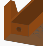
I actually just thought of a possibility for embedding it in the left leg, and hollowing out a chamber for securing it sideways into the leg. It looks like it would work and would be printable with minimal supports. seems like it would work and actually be better than my current location (except maybe trying to secure the nut on the inside of the barrel jack connector) .

Screenshot 2026-09-28 at 10.18.26 AM.png Screenshot 2026-09-28 at 10.18.48 AM.png


When I get back from my trip, I'll see about moving the Floppy screen and buttons, and re-doing the power inputs and testing the lighted power button.

If anyone knows of a good solution for pre-made momentary switches that can be wired in easily, and secured in some mounts in a 3d printed enclosure, let me know. I was thinking about these? I would wire them to be remote buttons for the 3 ESFloppy buttons on the LisaFPGA. Then add little buttons underneath the chin for navigating, with the LCD now exposed on the front of the case. Then I would seal up the opening on the back, and remove those buttons.

1790605435794.png

https://www.adafruit.com/product/44...w7nygIZXNhkvKhReXbNd_P8QXpscUIFAi2n-GWhE_-o_Q

Now that I'm thinking about it. I might be able to put the 12v input where those ESFloppy buttons are today. IF that and the screen is moved, it opens up the space on that side for the power. I'll tinker with it when I return. This gives me a lot of respect for engineers building physical devices...
 
Last edited:

KnobsNSwitches

Tinkerer
Nov 2, 2021
47
50
18
Ha. Yeah I used it as justification to get a second, larger 3d printer to be able to print without splitting! It is nice having a 350mm print bed printer.
Not to be a noob derailing this thread, but is it possible to print this on a smaller printer? Like a 256mm print bed?
 

wottle

Active Tinkerer
Oct 30, 2021
956
717
93
49
Fort Mill, SC
Not to be a noob derailing this thread, but is it possible to print this on a smaller printer? Like a 256mm print bed?
It is, but you’ll need to join the parts after the fact. My first test prints were on my BambuLab A1. I simply sliced it at a point where it would be a clean cut, printed some blocks I could use as glue supports, two on the back and one on the top and bottom. It’s not perfect and you’ll see the seam lines, but it would work.

I believe the height makes it possible to simply print each piece (front and back) as two parts.
Just make sure where you glue the blocks won’t interfere with the case parts coming together or where the LisaFPGA ports and board components are. Also make sure you don’t slice through any of the buttons.

I think I finally threw away my early test print boards but I can try to show you where I sliced the parts to make it easiest and least obvious.
 

KnobsNSwitches

Tinkerer
Nov 2, 2021
47
50
18
It is, but you’ll need to join the parts after the fact. My first test prints were on my BambuLab A1. I simply sliced it at a point where it would be a clean cut, printed some blocks I could use as glue supports, two on the back and one on the top and bottom. It’s not perfect and you’ll see the seam lines, but it would work.

I believe the height makes it possible to simply print each piece (front and back) as two parts.
Just make sure where you glue the blocks won’t interfere with the case parts coming together or where the LisaFPGA ports and board components are. Also make sure you don’t slice through any of the buttons.

I think I finally threw away my early test print boards but I can try to show you where I sliced the parts to make it easiest and least obvious.
Thank you! black friday approaches, a 3d printer is in my future.
 
  • Like
Reactions: wottle

wottle

Active Tinkerer
Oct 30, 2021
956
717
93
49
Fort Mill, SC
@KnobsNSwitches , I'd also be willing to print one and ship it to you at cost, assuming you aren't using this to justify said purchase of a new 3d printer! :)

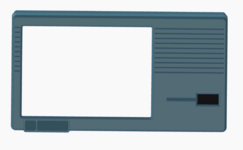
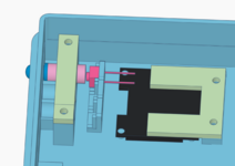
I got back from my trip and I'm trying to get this project across the finish line. I re-worked it to move the ESFloppy LCD to the front of the case (although I seem to have broken my LCD during the removal process, so if you choose to do this, be careful with the LCD when you're removing it from the L:isaFPGA). I also have moved the ESFloppy buttons to the chin of the case, right under the LCD so you can manipulate it from the front of the machine more easily.
Screenshot 2026-10-04 at 2.22.18 PM.pngScreenshot 2026-10-04 at 2.22.45 PM.png

Unfortunately, moving the LCD and the buttons (and the power LED) aren't necessarily for the faint of heart. You need to remove the existing power LED (under the power button), then solder wires to those pads, as well as two legs for the power switch, the left, select, and right ESFloppy switches. Then you need to solder on some header pins in the place of the removed LCD. I'm just using Dupont wires for connecting things. All these cables need to be removable because the LisaFPGA is screwed to the back case, and the ESFloppy buttons and the LCD will be screwed to the front case.
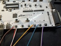
IMG_2625.jpeg


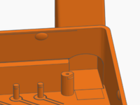
I've done a test print of just that section of the case and it worked well in terms of button fit and LCD position. I'm waiting for my replacement LCD and the switches to arrive before I print my official case pieces. With the ESFloppy LCD and buttons moving to the front, I now have a new back case that removes those buttons and the screen cut-out. It also relocates the power jack input to one of the legs (because the lighted power button needs to be placed where the old power button was) and adds the lighted power button that I used for the Pi version. The new bump for the power button makes the back no longer symmetrical, which I don't love, but I think it's a good compromise - the sideways oriented jack means my 12v USB-C power adapter won't be bent as harshly, and I added a master power rocker switch to the upper corner on the back so you can cut power to the LCD when not in use. That means multiple power switches/buttons (one master power switch, one switch on the LisaFPGA, and the Lisa power button).

I also added a few zip tie rings around the inside of the case to help with cable management. Flexible and basically free. Optional for people who want the wires to be better secured.
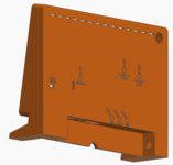
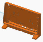
1791138788360.png Screenshot 2026-10-04 at 2.38.03 PM.png

Once my new LCD arrives, as well as the momentary switches, I should be able to call it a wrap on this.

 

wottle

Active Tinkerer
Oct 30, 2021
956
717
93
49
Fort Mill, SC
Got the switches in today and the button components work really well. The buttons barely stick out, so it is very subtle, but easily findable by touch.

Here's the new front plate. Also, I've spent some time trying to address one of my pet peeves about the LisaFPGA - it's support (or lack thereof) for more USB input devices. It basically only supported low speed USB HID devices with no hubs built in. This ruled out most wireless keyboards and mice, as well as every Apple USB keyboard (since they all have built in hubs). So my fork of the LisaFPGA software has full USB hub support as well as support for low and high speed USB devices. I've tested it on a variety of my USB devices and it worked on all of them.

The new front case with the buttons built in and ESFloppy screen on the front is really nice, and once I replace the LCD I broke during removal, I'll demo it with the new keys on the front chin of the device. I'm working on some improvements on the back case before I print - namely a way to access the microSD cards without opening the case and having to unscrew the LisaFPGA board to access them. I'm leaning towards an opening in the side of the case (with a cap that could pop on and off to cover it when not needing to access them. But I might add a pair micoSD extension that would allow me to cleanly mount to the side of the case and make it a cleaner look (just a thin opening for the microSD cards themselves. That just add complexity and cost and I feel like it may be overkill.

Here it is in action (minus a working ESFloppy screen).
 
Last edited:
  • Wow
Reactions: JDW

JDW

Administrator
Staff member
Founder
Sep 2, 2021
2,851
2,223
113
55
Japan
youtube.com
...my fork of the LisaFPGA software has full USB hub support as well as support for low and high speed USB devices. I've tested it on a variety of my USB devices and it worked on all of them.
Oh, bless you, @wottle !
I didn't want to mention that failing too much after having received my LISA-FPGA because I didn't want the creator or others to think me unhappy or ungrateful for the incredible device it is; but honestly, it was really sad I couldn't use any of the keyboards I had. I ultimately had to buy the recommended one from Amazon USA and have it shipped to Japan because Amazon Japan didn't sell it. It works, but having compatibility with vintage Apple keyboards will be great.

I've not flashed anything to my LISA-FPGA, so if you have any tips on how to perform your USB keyboard firmware upgrade, please let us know.
 

wottle

Active Tinkerer
Oct 30, 2021
956
717
93
49
Fort Mill, SC
Oh, bless you, @wottle !
I didn't want to mention that failing too much after having received my LISA-FPGA because I didn't want the creator or others to think me unhappy or ungrateful for the incredible device it is; but honestly, it was really sad I couldn't use any of the keyboards I had. I ultimately had to buy the recommended one from Amazon USA and have it shipped to Japan because Amazon Japan didn't sell it. It works, but having compatibility with vintage Apple keyboards will be great.

I've not flashed anything to my LISA-FPGA, so if you have any tips on how to perform your USB keyboard firmware upgrade, please let us know.
Sure. You don't need the screen adjustment changes, but you can install my fork and get the USB improvements by following the instructions in the "About this Fork" section of the readme here: https://github.com/wottle/LisaFPGA#about-this-fork-lisa-mini

Side advantage: if you haven't already flashed the latest changes from Alex (with ESFloppy functionality), you will get those changes along with mine.
 
  • Love
Reactions: JDW

JDW

Administrator
Staff member
Founder
Sep 2, 2021
2,851
2,223
113
55
Japan
youtube.com
Thanks for the link and the mention of those side advantages, which are great because I've never upgraded the firmware on my board.

QUESTION...
Your Github says this:
Image offset/alignment tuning and resolution modes, so the picture lands correctly in the case's screen opening.

Currently, I am using an HDMI cable to connect my board to my 48" TV, which works great.
If I flash your firmware, will it mess with the way it displays on my TV?
Meaning, should we only flash your fork if we are using the LCD required by this 3d Case Project?
 

wottle

Active Tinkerer
Oct 30, 2021
956
717
93
49
Fort Mill, SC
Thanks for the link and the mention of those side advantages, which are great because I've never upgraded the firmware on my board.

QUESTION...
Your Github says this:
Image offset/alignment tuning and resolution modes, so the picture lands correctly in the case's screen opening.

Currently, I am using an HDMI cable to connect my board to my 48" TV, which works great.
If I flash your firmware, will it mess with the way it displays on my TV?
Meaning, should we only flash your fork if we are using the LCD required by this 3d Case Project?
No, by default it will continue to display in the middle of the screen with 1080p output (using the 60/30Hz jumper to drive the refresh rate). My changes just add the ability to bring up an on screen menu to either shift where it displays (left or right) in the 1080p output, or also allows you to output a 1024x768 image (for using an iPad display). But if you don't change either of those settings, the video output will behave exactly as it does today. You'll just get the benefit of the new USB support.

Also, nothing I've done is permanent. If you didn't like my changes, you can always re-flash it to the main repo by Alex and my changes are removed.
 
  • Love
  • Like
Reactions: phunguss and JDW

wottle

Active Tinkerer
Oct 30, 2021
956
717
93
49
Fort Mill, SC
One thing I need to check on. Got some reason, I now get a message on power-up about the "Built in parallel port: unconfigured". I don't know if that is due to Alex's new ESProfile firmware (which I pulled into my fork), or if it's something about my changes. The solution is simply, just press 1 on the keyboard to select parallel port 1, but I want to ensure it's not something I've done causing it.

Unfortunately, I've stuffed mine into my Lisa Mini case, having just gone through making an assembly video, and I don't have the energy to pull it out to do a clean build with Alex's main branch to compare. I'll try to check it out this weekend.

Assembly guide if anyone wants to see what's involved in making one:
 

JDW

Administrator
Staff member
Founder
Sep 2, 2021
2,851
2,223
113
55
Japan
youtube.com
I've not flashed or watching any videos about flashing yet. But I take it there's no way to easily re-flash it while inside the case?
 

stepleton

New Tinkerer
Oct 25, 2025
28
17
3
One thing I need to check on. Got some reason, I now get a message on power-up about the "Built in parallel port: unconfigured". I don't know if that is due to Alex's new ESProfile firmware (which I pulled into my fork), or if it's something about my changes. The solution is simply, just press 1 on the keyboard to select parallel port 1, but I want to ensure it's not something I've done causing it.
It's not your fault, it's almost certainly a side-effect of one of Alex's changes to the main LisaFPGA code. His change revealed a bug in the Selector (the program that boots and gives you the hard drive image menu) that is almost impossibly unlikely to occur in a real Lisa, but that easily occurs on the LisaFPGA. Basically, the LisaFPGA sets uninitialised PRAM memory to all zeroes, while the real Lisa will have random values there instead. The Selector responds incorrectly to that all-zero configuration.

We discuss this in this part of the LisaFPGA thread on LisaList2.

It would be trivial to use AI to fix the Selector; the thread even describes a minimal fix. I am here to humbly ask that you don't do that though?

I have some time off coming up in December. I'm planning some improvements to the Selector, including fixing this bug. I want to do all of this work by hand, because I enjoy it; it's one of my favourite things to do. I'm looking forward to it. Until then, all you need to do is press 1 on boot, and everything works as it should. If you can just bear with me and do that for a little while longer, I'd appreciate it...
 

wottle

Active Tinkerer
Oct 30, 2021
956
717
93
49
Fort Mill, SC
I've not flashed or watching any videos about flashing yet. But I take it there's no way to easily re-flash it while inside the case?
Yeah, I considered making the USB-C port accessible while inside the case, but I have power wired into the USB-C port. Meaning even if I made the port location accessible, you'd need tp pry out the low profile usb-c connector then plug in the connection from the computer, and after try to re-insert the low profile connector through a small opening. As it stands right now, you'd just need to pop the shell open. (no screws required, friction fit), then remove 4 screws to lift the board to access the USB-C. So probably 2 minutes to access it for something that hopefully you won't need to do often.

I also considered adding switches to the back for the CPU speed toggles. Ultimately I decided that I would rather add it to my on screen menu than do the 3d modeling work and worry about having to align all 3 switches to make installing the board in the case possible. So changing the CPU speed can be done from the front of the device. I'll give it a shot today if I have time.

It's not your fault, it's almost certainly a side-effect of one of Alex's changes to the main LisaFPGA code. His change revealed a bug in the Selector (the program that boots and gives you the hard drive image menu) that is almost impossibly unlikely to occur in a real Lisa, but that easily occurs on the LisaFPGA. Basically, the LisaFPGA sets uninitialised PRAM memory to all zeroes, while the real Lisa will have random values there instead. The Selector responds incorrectly to that all-zero configuration.

We discuss this in this part of the LisaFPGA thread on LisaList2.

It would be trivial to use AI to fix the Selector; the thread even describes a minimal fix. I am here to humbly ask that you don't do that though?

I have some time off coming up in December. I'm planning some improvements to the Selector, including fixing this bug. I want to do all of this work by hand, because I enjoy it; it's one of my favourite things to do. I'm looking forward to it. Until then, all you need to do is press 1 on boot, and everything works as it should. If you can just bear with me and do that for a little while longer, I'd appreciate it...
Good to know I didn't introduce it - thanks for the confirmation. As long as it's not something new I did, I'll just use the manual workaround for now and wait for the future change to the selector. I'll note it in my documentation so others realize it's a known issue that has a fix on the way. Appreciate all the work you all are putting into it. I wish I had more knowledge in these areas and didn't have to have AI do much of the heavy lifting for me. Thanks again!