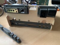
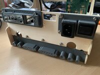
Well, thats also an option….not my first choice.
 There is still time to find a decent repetative way
A takky Mac…..
- Thread starter -SE40-
- Start date
-
Please can you read through and vote on the following proposition for changes to the board structure by clicking here.
You are using an out of date browser. It may not display this or other websites correctly.
You should upgrade or use an alternative browser.
You should upgrade or use an alternative browser.
Sure. Roger mentions 2 x 4 in his listing, so may be worth dropping him a mail to see if he's expecting them back in stock?There is still time to find a decent repetative way
No confusion,…
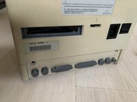
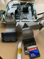
……. there are two 50 pin connectors now.
One is split for two connectors.
FDD and CD sound.(i believe)
Video is on the other side of the board.
All go to up the logic board connector.
Just trying to get these cables organized decently….
……. there are two 50 pin connectors now.
One is split for two connectors.
FDD and CD sound.(i believe)
Video is on the other side of the board.
All go to up the logic board connector.
Just trying to get these cables organized decently….
Couldn't find the reference about a mystery cable on your harness. Unless you've identified it, "extra" cable ought to be the TV Tuner interface I think.
Getting there!
Switch and cable positions are almost perfect!
A converted sfx could also be suitable as psu.
Attachments
@Trash80toG4 ….no mystery cables left
There is just one 2x4 flatband - audio CD- that needed connection. As the planned connector seems hard to get, its now aimed to be combined in the second 50 pin connector.
There is just one 2x4 flatband - audio CD- that needed connection. As the planned connector seems hard to get, its now aimed to be combined in the second 50 pin connector.
Was that the last to be identified or had you found it already?
Haven't got one handy, but there's an offset edge card (harness end on CD-ROM bar) to CD pins adapter I couldn't find in the exploded diagrams. Have you removed the CD Adapter from the harness or did you plug SCSI and power cables into it?
Haven't got one handy, but there's an offset edge card (harness end on CD-ROM bar) to CD pins adapter I couldn't find in the exploded diagrams. Have you removed the CD Adapter from the harness or did you plug SCSI and power cables into it?
@Trash80toG4 100% correct, slightly different CD-rom connector/harness mount …I suspect.
In the end its just an extension cable for the CD rom.
This should work, maybe obsolete also. IDE and the blue SCSI may replace fdd and CD-rom in the end.
Thought it may come in handy some day.
Yes, because of that option……perhaps
Blue SCSI can do that also - in time-?
using diskjockey? from onegeekarmy
I have to kidnap my wifes imac for that to try out…..
(edit it does ISO files)

Blue SCSI can do that also - in time-?
using diskjockey? from onegeekarmy
I have to kidnap my wifes imac for that to try out…..
(edit it does ISO files)
Last edited:
Yes, because of that option……perhaps
Blue SCSI can do that also - in time-?
using diskjockey? from onegeekarmy
I have to kidnap my wifes imac for that to try out…..
iMac has not used SCSI as the older iMacs used IDE/PATA, whereas the newer iMacs used SATA then mSATA SSD. Nowadays, iMacs use the latest SSD interface.
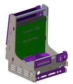
Yesterday evening I finished the final version for the cableshield layout! Next reprinted to fit…….
and I am satisfied now 🛠

With the previous version, the left two holes on the bottomshield where only off by 0,2 mm,
and pushing it in did cause it to get stuck/bend a little.
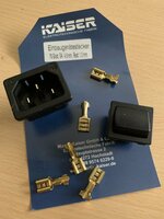
Moved also the switch and connector
down a bit and its centered now.
This part of the rebuilding process
was a drag to get it right
Ive put the AV control in the backside for now.
If all works well and its usefull,
it may be moved to the front.

and I am satisfied now 🛠
With the previous version, the left two holes on the bottomshield where only off by 0,2 mm,
and pushing it in did cause it to get stuck/bend a little.
Moved also the switch and connector
down a bit and its centered now.
This part of the rebuilding process
was a drag to get it right
Ive put the AV control in the backside for now.
If all works well and its usefull,
it may be moved to the front.
Attachments
Last edited:
@Trash80toG4 …. now the exact position is known for each connector…..how to move forward?
Where can I find these extension cables to fit?
Or must these be soldered up from loose components/old cables?

Anyone?
Sources?
Any input is welcome!

Where can I find these extension cables to fit?
Or must these be soldered up from loose components/old cables?
Anyone?
Sources?
Any input is welcome!
Drawing above is for a custom PCB setup. The tentacles dangling represent the wires from lopped off full length cables. Wires to be soldered into their respective thruholes on the adapter board sitting in place of the Compact Logic Board.
edit: doubtful, but you might be able to source panel mount solder cup terminated connectors?
edit: doubtful, but you might be able to source panel mount solder cup terminated connectors?
Last edited:

