retr01

Senior Tinkerer
Jun 6, 2022
2,469
1
778
113
Utah, USA
retr01.com
Hello!

I acquired a SE/30 in excellent condition. I have had a strong computer background, especially Apple since I was a kid. I am happy to be back into tinkering.

I saw on YouTube that Adrian Black showed how to do a video out from a Macintosh Classic from its analog board through RGB2HDMI. I realized that in the Mac SE and SE/30, the analog board (AB) was designed differently than in the Mac Classic and Classic II. Adrian's video is based on Classic’s AB. The SE and SE/30, as well as older compact Macs, do not have that AB design.

Thank you, @Stephen, for doing this! You did splendidly, and I appreciate that. I want to have the video out from the SE/30 like it was done back in the day to TTL output while I am waiting for @Zane Kaminski and the folks at Garrett's Workshop to come up with a new PDS video card for the SE/30 with a second PDS connector for a network card that I have. I would like to have this output set up.

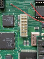
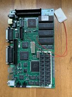
So, I purchased the Power R Model 2703 Video Adapter for Apple Macintosh SE or SE/30 off eBay. @Stephen, according to Power R's defunct website via the Wayback Machine (scroll down to the bottom of the page), this model has the exact specifications as 2702, only different connectors. Connecting the male end to the SE or SE/30 logic board (LB) and the cable from the female end from LB to the AB is straightforward.

Power R Model 2703.jpg
Power R Model 2702 2703 Specs.jpg

All I have to do is plug-in male to male dupont jumper cables in the black TTL header and solder one end to the RGB female connector as shown in the schematic created by @Stephen. Is that correct? Then, I would get the RGB2HDMI adapter with Pi Zero.

@Stephen can you update your GitHub page to include a clone version for the SE and SE/30 since it needs those types of connectors, as shown in the photo herein? I would be happy to let you know the result after doing this and if the results are favorable?

By the way, thank you, @JDW, so much for your beautiful videos on YouTube! I appreciate your clear explanations and showing the process. Those helped me a LOT to tear down my SE/30.
 
Last edited:

Stephen

BetterBit
Staff member
Founder
Sep 5, 2021
188
228
43
San Francisco
@Stephen can you update your GitHub page to include a clone version for the SE and SE/30 since it needs those types of connectors, as shown in the photo herein? I would be happy to let you know the result after doing this and if the results are favorable?
I'm not opposed — but one of the advantages of open source is that other people can spin off their own version! If no one wants to take a stab at this then I will make an updated version just for ✨ you ✨.
 
  • Haha
Reactions: retr01 and jcs

retr01

Senior Tinkerer
Jun 6, 2022
2,469
1
778
113
Utah, USA
retr01.com
Morning, @-SE40-!

Yes and no. It depends on various compact Macs' analog boards (AB) and logic boards (LB). Based on the differences, adapting to produce a 1-bit black and white (B/W) video output via (TTL) is done differently. One way is to use a vintage or modern adapter. Another way is to wire the connection based on the required matching pinouts. First, the differences between the ABs will be shown. Second, the location where the adapters are plugged differ. Third, the alternative wiring connection differs as well.

1. Here are the general differences between the ABs of the compact Macs. The first two ABs do not have taps to produce the B/W video output as it is done on the LB. However, the third AB has video output taps.


2. Vintage closed-source and modern open-source adapters send the 1-bit B/W video output via TTL to the DE-15 (DB-15) or DE-9 (DB-9) RGB connector. From there, a vintage RGB monitor can be connected, or a modern monitor can be connected through modern adaption such as Extron or RGB2HDMI. Pictures, links, and explanations are currently in this thread.

3. Alternative wiring connections can be made after identifying the correct video pinouts between the connections. For example, Adrian has shown an excellent method for the Classic and Classic II on a YouTube video:


As for COLOR video output, the 128k, 512k, Plus, SE, Classic, and Classic II generally require a SCSI external video adapter, as an example explained in this message. The SE/30 is the only 030 compact Mac with a 030 PDS slot capable of utilizing color video cards. As pointed out in another message earlier, the SE/30 can display 256 grays on the internal CRT monitor with an adapter.

I am not sure if there are LC PDS slot color video cards for the Color Classic and Color Classic II to drive external color video.
 
Last edited:
  • Like
Reactions: -SE40-

-SE40-

Tinkerer
Apr 30, 2022
416
161
43
The Netherlands
pin.it
Good morning to you too….although its evening here ✅

Thank you very much for your extended explanation.
This is much appreciated!
I think others also will find this info very usefull too👍

Somehow I did come to option 3.
I saw the vid of ADB, and got me thinking…..
Would it be possible to combine the CL II board with the RGB to HDMI board and a nice LCD and make Hartmuts 💓 laptop what never was.
No analog board …. is that possible?
Adding a Lipo pack should last a while on mobile use.
This board is recapped and working fine, so that is a good start.
I could then recreate Hartmuts “laptop” enclosure, and make it fully functional.

Would that not be supercool?


DD469A52-6B34-4FE2-9924-9A0F18DE0F1E.jpeg
 

Attachments

  • 41A42AF3-6086-403F-A2A8-91640C604791.jpeg
    41A42AF3-6086-403F-A2A8-91640C604791.jpeg
    1.3 MB · Views: 64
  • DE78FE20-9FBC-4DD8-BEEE-659D4C2949CF.jpeg
    DE78FE20-9FBC-4DD8-BEEE-659D4C2949CF.jpeg
    1.8 MB · Views: 74
  • Like
Reactions: retr01

retr01

Senior Tinkerer
Jun 6, 2022
2,469
1
778
113
Utah, USA
retr01.com
Yeah! Super cool! :cool:

@-SE40-is that the Classic II logic board? I can see the memory SIMM fashion and the 030 CPU. What are the wires for? :confused:

As for one of Hartmut's portable Mac designs, I think that is possible with the right logic board and video TTL output. Fabricate the case, keys, LCD housing, hinges, etc., via 3D printing. 👍:geek:

Might the keyboard be one of the most expensive things, though? I have read that custom keyboards are insanely costly, not because of the keys but the switches? 🤑

Is that a project you want to do as a new thread? Do we need a new category for "the Vaporized Macs" here on Tinker Different? 🤔
 

-SE40-

Tinkerer
Apr 30, 2022
416
161
43
The Netherlands
pin.it
Hi, retro01!

indeedClassic II board.
This is the board of my first Mac.
I like it for its compactness, and so usable for this purpose.
At least if I can get it to work with a flat panel display without too many extra parts.

its not a project yet, until its electronics side is made /proven to work.

its actually a similar sort of challenge as with
Erics Color Classic.
But with another gen board.

For the keyboard I have Conversion of a original keyboard with custom made keys in mind.
The enclosure I would love to create a mould for from high quality 3D printed shells….but thats still a long way to go.
A man can dream…..😇

The wires are temporarely for a 2032 battery soldered on BTW.
 
  • Like
Reactions: retr01

alxlab

Active Tinkerer
Sep 23, 2021
287
305
63
www.alxlab.com

Here's a conversation with Zane about using a Pico Pi to convert the video signal from a compact Macintosh (128K, 512K, SE, SE/30, Classic, Classic II) to something more usable by modern screens. Maybe this will give some inspiration to someone.

alxlab-zone66x02/07/2022​

Was contemplating the use of a Pi Pico for outputting the video of a compact b/w Mac

  1. [12:52 PM]
    the ADC on the pico should be good enough to read the h amd v sync

  2. [12:52 PM]
    the video signal is just 1-bit


  3. Zane Kaminski02/07/2022​

    Well for the Mac it’s all digital so no need for an ADC

  4. [12:52 PM]
    Yeah

  5. [12:53 PM]
    But there remains the problem of when to sample the pixel

  6. [12:53 PM]
    How do you get your 15.6672 MHz clock exactly lined up with the video output so that you sample in the middle of the pixel


  7. alxlab-zone66x02/07/2022​

    Yeah that's where my knowledge of how this stuff is handled fails me


  8. Zane Kaminski02/07/2022​

    You can tap the board or build a PDS card but that’s not as good
  9. alxlab-zone66x02/07/2022​

    there must be some hacky cheap way to handle the straight output
  10. Zane Kaminski02/07/2022​

    My best idea for the Mac is to sample at 50 MHz and your program knows that there are 50/15.6672 sampled pixels per actual pixel and you go by that factor, adjusting one pixel forward or back according to when your software sees a transition

  11. [12:56 PM]
    So like an 01010101 pattern on the Mac will be stretched out into: 000111000111000111

  12. [12:56 PM]
    But eventually there will be 4 in a row not 3

  13. alxlab-zone66x02/07/2022​

    oh yeah the scaling is no prop

  14. [12:56 PM]
    I would use 1024 x 768

  15. Zane Kaminski02/07/2022​

    You sorta watch for that to keep your thingy in sync
  16. [12:56 PM]
    No no not on the screen in the end
  17. [12:56 PM]
    Like coming into your gizmo
  18. alxlab-zone66x02/07/2022​

    ah ok for detection of the actual pixels you mean

  19. Zane Kaminski02/07/2022​

    Since the pixels change at 15.6672 MHz but you sample at approximately 3x that. So your software sees 3-4 pixels for every one the Mac puts out

  20. [12:57 PM]
    Yeah
  21. Androda02/07/2022​

    Pi pico's PIO units ought to be able to sample the digital signal

  22. Zane Kaminski02/07/2022​

    And you sorta watch and keep it synced

  23. Androda02/07/2022​

    Those things are nuts, and sample every clock cycle


  24. Zane Kaminski02/07/2022​

    Well if we can sample at 3x the pixel speed we build something like a UART to capture the pixels

  25. [1:00 PM]
    In software though

  26. [1:00 PM]
    Yknow how a UART doesn’t have the bit clock, you have to oversample and the UART figures out which bit is which and there’s the whole concept of tolerable baud rate error

  27. [1:00 PM]
    That’s my “only an RPi” strategy for this


  28. alxlab-zone66x02/07/2022​

    actually my knowledge on any of these protocols is like 0 but what your saying makes sense
  29. [1:02 PM]
    what if we add an external clock that gives us the 15.66672?

  30. [1:02 PM]
    would that make our life easier?

  31. Zane Kaminski02/07/2022​

    It’ll wander
  32. [1:03 PM]
    So basically your software aims to watch for hsync to indicate the start of the line, take in 1634 pixels (512 * 50/15.6672) and then sorta process that bitstream into 512 actual pixels

  33. [1:04 PM]
    I guess it’s possible, just sorta keep track of your fractional pixel position. Shouldn’t need to adjust forward or back during a line

  34. alxlab-zone66x02/07/2022​

    actually if we sample at 3x the pixel clock then could auto correct like you said

  35. [1:04 PM]
    a pixel would have 3 of the same value

  36. Zane Kaminski02/07/2022​

    Yes but you can never depend on it being exact

  37. [1:04 PM]
    So it will be 2.9something or 3.0something

  38. [1:05 PM]
    So since that’s weird already I figured exactly 3x doesn’t have much of a point and we can advance by 3.19 or whatever

  39. [1:06 PM]
    and just round to the nearest pixel, plus detect if there is a change too close to the current sample position and skip one forward or backwards

  40. alxlab-zone66x02/07/2022​

    yeah add a delay or something

  41. [1:06 PM]
    it would be really interesting if it worked half decently

  42. Zane Kaminski02/07/2022​

    I can’t figure out how to get the bits into the pi though

  43. [1:08 PM]
    Like we want it to just be dumping what it sees on the wire straight into memory in the background of other processing but idk if it has a peripheral that can do it

  44. [1:08 PM]
    If not then we have to involve a little FPGA to buffer it in a FIFO so the CPU can get a bunch of bits out all at once

  45. alxlab-zone66x02/07/2022​

    well there would be some processing of the signal

  46. Zane Kaminski02/07/2022​

    I just mean to read the oversampled 50 MHz pixels

  47. [1:09 PM]
    Then we format those right and actually put em in video ram
  48. alxlab-zone66x02/07/2022​

    can just use the standard io libs?

  49. Zane Kaminski02/07/2022​

    Not sure
  50. [1:12 PM]
    Can we make it like do a 1634 bit spi transaction and dump it in memory for processing?

  51. [1:12 PM]
    That’s my best guess

  52. alxlab-zone66x02/07/2022​

    yeah guess it would be a matter of trying out stuff at this point

  53. [1:15 PM]
    Gives me an idea that I'm not totally dreaming in color

  54. Zane Kaminski02/07/2022​

    Yeah here we go
  55. [1:15 PM]
    https://github.com/rsta2/circle/blob/master/sample/23-spisimple/kernel.cpp
    GitHub
    circle/kernel.cpp at master · rsta2/circle
    A C++ bare metal environment for Raspberry Pi with USB (32 and 64 bit) - circle/kernel.cpp at master · rsta2/circle
    circle/kernel.cpp at master · rsta2/circle


  56. [1:16 PM]
    So at every line we basically start a really long SPI transaction and collect the results on the next line

  57. [1:16 PM]
    Should work!
  58. alxlab-zone66x02/07/2022​

    interesting!

  59. [1:17 PM]
    so basically the hsynch would trigger that

  60. Zane Kaminski02/07/2022​

    Yeah but there’s a gotcha

  61. [1:17 PM]
    I think we have to start it on the previous line’s end

  62. [1:18 PM]
    And get a bunch of garbage in the beginning

  63. [1:18 PM]
    Otherwise we’ll miss the first few pixels

  64. [1:18 PM]
    Because interrupt latency, etc.

  65. [1:19 PM]
    But then there’s a new problem... we need to capture hsync in time with the SPI bitstream so we can know when the active video region starts

  66. [1:23 PM]
    Well the rpi SPI can do 125 MHz so we can like double up samples with some external logic

  67. [1:23 PM]
    Even bits are hsync, odd bits are pixel color

  68. alxlab-zone66x02/07/2022​

    ah 2x spi interfaces on the pico

  69. Zane Kaminski02/07/2022​

    Ooh yes maybe

  70. alxlab-zone66x02/07/2022​

    but we have vsync as well

  71. alxlab-zone66x02/07/2022​

    I need to verse myself more on how the different protocols work

  72. [1:46 PM]
    right of course the hdmi out will take up some io also

  73. [1:46 PM]
    https://github.com/Wren6991/Pico-DVI-Sock

    GitHub
    GitHub - Wren6991/Pico-DVI-Sock: A DVI Sock board for Pico
    A DVI Sock board for Pico. Contribute to Wren6991/Pico-DVI-Sock development by creating an account on GitHub.

  74. [1:46 PM]
    Like the silkscreen "NOT HDMI just sparkling DVI"
    🙂


  75. Zane Kaminski02/07/2022​

    Vsync is easier since it's slow

  76. [1:48 PM]
    2 chips

  77. [1:48 PM]
    Here we go
    Image


  78. [1:48 PM]
    This gizmo will mux the hsync and intensity on to the same wire

  79. [1:49 PM]
    The catch is you don't know which will come first, the hsync or the video hahahahah

  80. [1:49 PM]
    I can add some more to fix that

  81. [1:50 PM]
    Yeah that's easy to fix

  82. [1:50 PM]
    So basically you get the RPi to do a 125 MHz SPI transaction (fast but it can do it), send SCK in there, and then it alternates VID and HSYNC on MISO which goes back to the RPi


  83. alxlab-zone66x02/07/2022​

    lol this is already more advance than my current level of electronic design


  84. Zane Kaminski02/07/2022​

    the 74LVC1G57 is basically a mux


  85. alxlab-zone66x02/07/2022​

    what the idea between using the same SPI vs two separate I/O? (edited)


  86. Zane Kaminski02/07/2022​

    Well then you know for sure they are exactly lined up in time

  87. [1:53 PM]
    Who knows how long the function to start an SPI operation takes, probably more than 1 Mac pixel time


  88. alxlab-zone66x02/07/2022​

    the hsync front porch and back porch is supposed to be pretty long so maybe it's not a problem

  89. [1:54 PM]
    http://www.waveguide.se/?article=compact-mac-video-adapter

    www.waveguide.se
    Compact Mac video adapter « waveguide.se
    [img=mac-se-video-bmva.jpg] For many years I have had an old Macintosh SE logic board that was scrapped out from an old Apple repair shop. Someone had broken the SIMM sockets at some point by snapping the retaining clips at the ends. A common problem u...

  90. [1:54 PM]
    he mentions "The horizontal signal is also unusually long and extends well into the visible area of the video lines."


  91. Zane Kaminski02/07/2022​

    Interesting!!

  92. [1:55 PM]
    Well at least it's constant


  93. alxlab-zone66x02/07/2022​

    on a normal vga signal you got lots of extra not drawn pixels at the begining and end of a line


  94. Zane Kaminski02/07/2022​

    So the time-correlation of the hsync to the video signal is still important

  95. [1:56 PM]
    We just have to find the hsync transition and then go backwards some fixed amount instead of forward

  96. [1:57 PM]
    All this depends on starting at the end of the previous line of course


  97. alxlab-zone66x02/07/2022​

    as long as the hsync isn't so far off as to go in between lines it should be ok


  98. Zane Kaminski02/07/2022​

    Yeah shouldn't be

  99. [1:59 PM]
    Ooh and the guy who wrote that article has a picture of the artifact we must avoid (edited)

  100. [1:59 PM]
    His monitor is sorta skipping pixels wrong

  101. [1:59 PM]
    Image


  102. alxlab-zone66x02/07/2022​

    yeah that's kinda cool his monitor actually output something


  103. Stephen02/07/2022​

    this solution is very comparable to the power-r adapter. Right?


  104. Zane Kaminski02/07/2022​

    Yeah


  105. alxlab-zone66x02/07/2022​

    mine just says hsync out of range


  106. Zane Kaminski02/07/2022​

    Should just be a passthrough


  107. elemenoh02/07/2022​

    @Zane Kaminski would your widget have digital or analog video out?


  108. alxlab-zone66x02/07/2022​

    at first I was thinking VGA out but if you dealing with all digital why bother going analog?

  109. [2:02 PM]
    seems simpler to just do dvi with a pi pico anyhow


  110. Zane Kaminski02/07/2022​

    So umm, we start the SPI thing at the end of the line, wait until the next line, find the hsync transition, go backwards some fixed amount to find the first pixel, then sample each pixel by going forward 62.5/15.6672 (approx 3.989) in the buffer and copy all 512 of that line into the back buffer in preparation to frame-skip copy into the actual video buffer to avoid tearing


  111. [2:03 PM]
    ^ that's the algorithm
 

retr01

Senior Tinkerer
Jun 6, 2022
2,469
1
778
113
Utah, USA
retr01.com
That is an interesting conversation, @alxlab. :)

I agree this is comparable to the Power R series of adapters, including 2702 and 2703 that @Stephen and myself have.

So, is it possible that simply using the Pi Pico as a video signal converter to become an alternative to RGB2HDMI with Pi Zero? My only concern is, can enough data be placed with on the Pi Pico to have full featured OSD menus show up on a modern display, many adjustments, varying video signals, etc? The Extron, RGB2HDMI, and other RGB to whatever video signal converters have OSD displayed on modern screens.

On the other hand, this is an excellent start to have a signal conversion that just works, requiring less components that are readily available, and cheaper without needing adjustment by the end user.
 
Last edited:

alxlab

Active Tinkerer
Sep 23, 2021
287
305
63
www.alxlab.com
That is an interesting conversation, @alxlab. :)

So, is it possible that simply using the Pi Pico as a video signal converter to become an alternative to RGB2HDMI with Pi Zero? My only concern is, can enough data be placed with the Pi Pico to have full featured OSD menus show up on a modern display, many adjustments, varying video signals, etc? The Extron, RGB2HDMI, and other RGB to whatever video signal converters have OSD displayed on modern screens.
Sorry I wasn't clear enough. This discussion was to make the cheapest purpose built converter to just output video from a compact Macintosh which is 512 x 384 and 1bit.

Using the analogy of slicing bread, sure you can use an expensive Swiss Army Swiss Champ XXL (RGB2HDMI) with a bunch of extra tools you won't need or you can just use a dollar store knife (PI Pico or whatever low cost microcontroller will do the job) for a fraction of the cost.

The RGB2HDMI has the harder job of trying to handle anything thrown at it. For the compact Macs we're dealing with a know quantity so hopefully we could try to make a less complex, plug and play and cheaper device.
 
Last edited:

-SE40-

Tinkerer
Apr 30, 2022
416
161
43
The Netherlands
pin.it
Pico VGA……wow!

This would be great as the regular pi’s seem hard to get.
Also the smaller size is a big plus for Hartmut’s laptop.
So any pico pi will do?
Sounds almost to good to be true🍀

EF91CFE2-C8B1-4CBA-8BE6-54C5E4A2A50F.jpeg


Ive found this list for the classic I and II 14 pin connector…
Would I be making connection directly for pin 4-5-6 that should do the job?

I sure have some reading todo😇
 

retr01

Senior Tinkerer
Jun 6, 2022
2,469
1
778
113
Utah, USA
retr01.com
Ive found this list for the classic I and II 14 pin connector…
Would I be making connection directly for pin 4-5-6 that should do the job?
So, I have a question @-SE40-. Where on the logic board is this connector? :unsure: Is it the same one that connects to the harness from logic board to the analog board?
 

Zane Kaminski

Administrator
Staff member
Founder
Sep 5, 2021
266
462
63
Columbus, Ohio, USA
Thank you, @alxlab, @Stephen, and @Zane Kaminski! You guys are awesome! :D(y)

Is there a GitHub repo with a tentative schematic of this Pico Pi approach?
I would say it's not a schematic-heavy kind of project. Regarding the algorithm I described:

"Start the SPI [transfer] at the end of the line, wait until the next line, find the hsync transition, go backwards some fixed amount to find the first pixel, then sample each pixel by going forward 62.5/15.6672 (approx 3.989) in the buffer and copy all 512 of that line into the back buffer in preparation to frame-skip copy into the actual video buffer to avoid tearing."

The first thing would be to create some kind of simulation to try out the method before actually implementing the hardware. We would want to test the algorithm against many combinations of small frequency and phase differences between the Mac and Pi clocks to make sure it recovers the pixels crisply in all cases.
 
  • Like
Reactions: retr01