Need solution for HDI-45 to DB-15 connectors for video out

wottle

Active Tinkerer
Oct 30, 2021
596
333
63
47
Fort Mill, SC
OK, I've been working through my PowerMac 61xx machines that I picked up in my filthy haul a few weeks back. I've successfully built some replacement Y adapters for the ones with a DOS card, but I now have a bigger problem. I currently only have a single HDI-45 adapter that I had with my 6115CD. So I expect I'll have around ten 61xx machines when all is said and done and I'd like to be able to pass them along to others with most of what they need to connect to a monitor and use it (I won't have enough ADB keyboards either, but those are easier to come by / already have).

So, does anyone have a bunch of extras of these they'd be willing to sell, or better yet, has anyone figured out a way we can make a new adapter out of readily available parts? I saw a post oin 68kmla (https://68kmla.org/bb/index.php?threads/solutions-for-hdi45-to-vga-or-db15.39202/page-2) about the posibility of a PCB to get the right pin spacing and I love that idea, but I have no PCB design skills and doubt I could make one correctly.

I was thinking of basically two PCBs. One that would mimic the pinout of the HDI-45 port. You would simply solder in the necessary pins, with wires soldered to the back side. a second PCB would accept those wires and have them go to a DB-15 port. A 3d printed case could hold both PCBs and provide a smaller replacement for all of us who are now missing adapters.

Anyone have a similar need or have tackled this issue?
 

wottle

Active Tinkerer
Oct 30, 2021
596
333
63
47
Fort Mill, SC
OK, so I think I may take a different approach. I think a more practical approach may be to build an adapter to mount a DB-15 port in the place of the HDI-45. It won't look as nice from the back, and you'd lose the ability to plug into that one AudioVision14 monitor, but I doubt many would care, and if you are one of the few with that monitor, you wouldn't need to do this replacement.

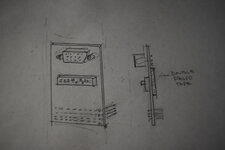
Anyway, so I was thinking of mocking up two boards (I don't think I can route all the traces and fit the through holes in the right spots to manage this with a single board. But there's room on the side of the connector, so I was thinking I'd make two boards, with seven 2mm spaced headers on each side. The bottom board would have pins for the HDI-45 connector on the logic board. The top board would have pin locations for a DB-15 connector. The pins on the side would simply transfer the signal between the two boards

1736390433678.png


This would allow me to more easily route the traces. I actually looked at the spacing of the pins and it appears I might be able to fit the 2 rows of pins for the DB-15 connector in between rows of the HDI-45 connector, but I'm not sure that would leave me enough room for the traces... The pads for the holes might simply not allow for it.

I'm hoping even with the extra height of the second board, the connector would still be low enough to fit through the opening of the existing hole for the HDI-45 connector. I'm planning on stumbling around in Eagle this weekend to see if I can mock up two versions. One using the two board approach, and another using the single board.
 
  • Like
Reactions: eric

Trash80toG4

Active Tinkerer
Apr 1, 2022
967
279
63
Bermuda Triangle, NC USA
I looked into this a loooong time ago for my 6100. What I came up with was a "periscope" PCB. with built in VGA adapter that mounts to the case with double sided tape or Velcro. *****

Never determined the pin spec for the HDI-45 monstrosity on the bottom of the board, likely header rows are available, but you really only need 15 pins, no?

DSC_1451.JPG

Sorry about the oversize file, image editing workstation down ATM.

Lucky here, the only NuBus PPC I really care about is my decked out Radius 81/110. With killer TPDs in their lineup, that beauty has DA-15 on board!


***** Neanderthal hacker that I am, washers, nuts and bolts would be employed. :p
 
Last edited:
  • Like
  • Love
Reactions: eric and wottle

phipli

Tinkerer
Sep 23, 2021
200
155
43
It would be easier to desolder the connector from the logic board and replaced it with an L-shaped bracket that presented a standard apple or VGA port on the back. Way easier to pick up the contacts on the logic board than at the connector end.
 

wottle

Active Tinkerer
Oct 30, 2021
596
333
63
47
Fort Mill, SC
It would be easier to desolder the connector from the logic board and replaced it with an L-shaped bracket that presented a standard apple or VGA port on the back. Way easier to pick up the contacts on the logic board than at the connector end.
Yeah, I have a test PCB on the way that would allow me to match the pin layout of the connector, but there are some challenges, like making the connector durable to handle being plugged in and unplugged, getting alignment perfect to not bend pins on insertion, etc. that’s why I think I’m going to try the approach of removing the connector and replacing it with a DB-15 connector. I'd prefer to not have to damage the back panel, so my top goal would be to build a 2 layer PCB that can mate the logic board to a DB15 connector with all 14 of the pins (and ground) connected properly.

The other challenge I need to figure out is making the add on board stable enough to handle the force of the connector being pushed in and pulled out repeatedly. Fortunately there are 4 ground connections on the corners that I'm hoping I can use to stabilize the board.
 

Trash80toG4

Active Tinkerer
Apr 1, 2022
967
279
63
Bermuda Triangle, NC USA
Since your stated purpose is to pass these machines along to other folks in the community, I think you might well reconsider my suggestion?

Some folks might want to keep the mobo cherry, some may want to keep the case cherry and some might want to pony up the bucks to source the real deal (gawdaweful as it may be) conversion cable from the ID10T crew at Apple. :rolleyes:

In any case, they may wish to malign the case by drilling holes for bolting up the adapter I suggested to the backplane or deal with the foibles of sticky-tape/Velcro mounting to keep it bone stock or what not?

In any case, KISS, reduce any modification to the machines to the minimum, avoiding the support of modifications to the machines at all costs.

YMMV ;)
 

phipli

Tinkerer
Sep 23, 2021
200
155
43
Since your stated purpose is to pass these machines along to other folks in the community, I think you might well reconsider my suggestion?

Some folks might want to keep the mobo cherry, some may want to keep the case cherry and some might want to pony up the bucks to source the real deal (gawdaweful as it may be) conversion cable from the ID10T crew at Apple. :rolleyes:

In any case, they may wish to malign the case by drilling holes for bolting up the adapter I suggested to the backplane or deal with the foibles of sticky-tape/Velcro mounting to keep it bone stock or what not?

In any case, KISS, reduce any modification to the machines to the minimum, avoiding the support of modifications to the machines at all costs.

YMMV ;)
No need to drill holes in the case. An L-shaped bracket with two right angle triangles would provide plenty of support. You could make the whole thing out of PCB. As mentioned, there are four ground tabs already there for mechanical support (they're already used as such by the existing connector). You'd just need to find the balance of thermal mass and rigidity.... and have a good soldering iron.

I never drill holes in stuff I can't buy new, I tend to make new parts, but I don't consider removing a port as a permanent change. I could always put it back. Besides... lets be honest, it is an improvement. Almost nobody wants a HDI45 connector on their 6100.

1736520187160.png


Obviously ignoring the scruffy PCB traces that I'm not going to spend ages sketching in any reasonable way.

I should have drawn the triangles key'd through the base PCB into the ground points on the logic board. But I didn't.
 

Trash80toG4

Active Tinkerer
Apr 1, 2022
967
279
63
Bermuda Triangle, NC USA
You don't need the vertical members for such a design. Use Right Angle HD-15 connector and build the VGA conversion into your board. Gotta pop the top to flip the switches, but that's easy on the pop-top 6100.

A lot of folks want to keep the logic boards intact, some would gladly pony up the bucks for that ridonkulous Apple conversion cable. Desoldering the connector to solder an internal adapter board would be a lot of work for wottle to pass machines on from his newly acquired Moras-o-Macs. ;)

@wottle avoid using a Mac DA-15 connector at all costs. Definitely don't want to hang a VGA Adapter off any internal adaptation, strain relief nightmares to be had there.
 

Trash80toG4

Active Tinkerer
Apr 1, 2022
967
279
63
Bermuda Triangle, NC USA
Yer killin' me here guys! :p Just had to pull the 6100 board to see what's going on. There's plenty of clearance for a horizontal PCB with RA HD-15 VGA connector to pop out the back. There's even a handy bolt-down hole right next to the highest IC to be cleared behind the connector.

If the IC is still too high, just have a hole or notch in the PCB for it to pop its head aboveboard. Looks good for any hot air rework station/soldering iron jockey.
 

phipli

Tinkerer
Sep 23, 2021
200
155
43
Yer killin' me here guys! :p Just had to pull the 6100 board to see what's going on. There's plenty of clearance for a horizontal PCB with RA HD-15 VGA connector to pop out the back. There's even a handy bolt-down hole right next to the highest IC to be cleared behind the connector.

If the IC is still too high, just have a hole or notch in the PCB for it to pop its head aboveboard. Looks good for any hot air rework station/soldering iron jockey.
That's good, if the opening is flush with the board then it is even easier.

I don't quite know what chips you're talking about though, isn't it just the HDI-45 connector going on between the board edge and the connector pins?
 

Nycturne

Tinkerer
Dec 18, 2024
44
27
18
I don't quite know what chips you're talking about though, isn't it just the HDI-45 connector going on between the board edge and the connector pins?

ICs on the 6100 logic board. If your goal is to build a PCB that will go straight to VGA, you will need the adapter logic built in, and thus some space is needed to fit it all in. I think they are commenting it should be straight forward to let the PCB sit above the ICs if you need the space.
 

phipli

Tinkerer
Sep 23, 2021
200
155
43
ICs on the 6100 logic board. If your goal is to build a PCB that will go straight to VGA, you will need the adapter logic built in, and thus some space is needed to fit it all in. I think they are commenting it should be straight forward to let the PCB sit above the ICs if you need the space.
Ah, no, you don't need anything other than some traces and a single diode to adapt from PowerMac video to VGA. The adapters with switches are only needed for older macs, and even they just have like, two diodes in them, unless you're messing with sync and auto detection. Here is the required circuit:

1736548682559.png
 

Nycturne

Tinkerer
Dec 18, 2024
44
27
18
To me, that's still adapter logic (perhaps circuit is more precise). Even the old ones didn't exactly have much in the way of smarts.

But ultimately, the comment was that there should be plenty of room to do whatever you need with a PCB, as it should be straight-forward to work around the ICs on the logic board if needed.
 

Trash80toG4

Active Tinkerer
Apr 1, 2022
967
279
63
Bermuda Triangle, NC USA
You'll want to make the PCB about 50mm deep and about 35mm wide so it reaches the handy bolt down/standoff hole behind at the right edge of the connector. housing
. . . ______
___| . .. 0 | <- standoff/boltdown
| . . . . . . . |
| . . . . . . . |
|_________| <- rear of case
 
Last edited:

wottle

Active Tinkerer
Oct 30, 2021
596
333
63
47
Fort Mill, SC
Appreciate the guidance. While I do agree that a VGA output would be ideal, 1. I'm not sure how you'd connect traces on PCBs at a right angle. Pads that line up at the edge of each board? I may see if I can make up a board that simply gives me a DB-15 connector and I'll use the adapter. Also, it allows me to still use my Dos Compatible card. It's fully reversible and it will be easier to remove since I will only be soldering a fraction of the pins.

Also, I don't plan on doing this for all the machines I'm going to be offloading (I expect I'll have about 8), but I want to at least have a solution for the one I plan to keep (one of the DOS Compatible ones). And if I can make the adapters pretty easily, I can at least give them to the new owner to install if they want. Or I could probably install them for a bit extra (removing that HDI-45 connector was a bear). If I cannot make all the pins work on the single board adapter, I may look into the 90 degree board assembly, along with possibly making a VGA output version.

Or possibly go back to my original idea, which was a plug in adapter that would leave the logic board fully untouched. I just don't believe I have the 3d modeling skills to make it work. We'll see, but with that, it would be easy to make two versions, one with the VGA/SVGA conversion, and one without.

I will say, I played around with the Quadra 650 with the older 58x Reply card and it was so much nicer to be able to simply plug it into the DB-15 port without the adapter. I need to look into what other machines the Houdini II cards can work in...
 

NJRoadfan

New Tinkerer
Feb 6, 2022
29
9
3
I'd solder on a PCB directly on top of the footprint of the removed HDI-45, just push the pins directly into the holes on the board and use any lugs to stabilize it. It'll likely be a double sided board depending on the pin routing. There may be enough room to direct mount a right angle VGA HDI-15 to the board as well.
 
  • Like
Reactions: wottle and Nycturne

wottle

Active Tinkerer
Oct 30, 2021
596
333
63
47
Fort Mill, SC
I'd solder on a PCB directly on top of the footprint of the removed HDI-45, just push the pins directly into the holes on the board and use any lugs to stabilize it. It'll likely be a double sided board depending on the pin routing. There may be enough room to direct mount a right angle VGA HDI-15 to the board as well.
Yeah, that’s my preferred option. PCB design isn’t my forte, so I’m trying to figure that out as I go. Hoping a dual layer board can give me enough room to route the traces in the gaps.
 

phipli

Tinkerer
Sep 23, 2021
200
155
43
You'll want to make the PCB about 50mm deep and about 35mm wide so it reaches the handy bolt down/standoff hole behind at the right edge of the connector. housing
. . . ______
___| . .. 0 | <- standoff/boltdown
| . . . . . . . |
| . . . . . . . |
|_________| <- rear of case
Nah, you don't need the mounting point. Without the huge adapter you'll be putting less strain on the connector than the stock design which was mostly ok with just the solder mountings. Keep it small, keep it cheap.

To me, that's still adapter logic (perhaps circuit is more precise). Even the old ones didn't exactly have much in the way of smarts.
Ok, but just to warn you, that isn't what logic means in electronics, or IC (Integrated Circuit) (not your words, but the ones you were explaining) - logic means boolean operations usually, or more complex chips made out of multiple boolean operations etc. IC on the other hand means a single package with multiple discrete parts rolled into one, at its absolute most basic, say two transistors in a single component, or perhaps an integrated RC filter That circuit could fit in about a 10mm square area of PCB without breaking a sweat. The connectors and distance to travel define the area required.
 

Nycturne

Tinkerer
Dec 18, 2024
44
27
18
Ok, but just to warn you, that isn't what logic means in electronics, or IC (Integrated Circuit) (not your words, but the ones you were explaining) - logic means boolean operations usually, or more complex chips made out of multiple boolean operations etc. IC on the other hand means a single package with multiple discrete parts rolled into one, at its absolute most basic, say two transistors in a single component, or perhaps an integrated RC filter That circuit could fit in about a 10mm square area of PCB without breaking a sweat. The connectors and distance to travel define the area required.

You don’t know my background, and I don’t know yours, so can we chill with jumping down each other’s throats here?

I only jumped in to clarify someone else’s argument, and I’m being made to feel like I’m now making that argument. This is a rabbit hole that only serves to pull away from the original idea from the other poster: *IF* you need the space, the space is there. Yes, I didn’t use precise language here, which I already admitted, so please just take a breath.
 

phipli

Tinkerer
Sep 23, 2021
200
155
43
You don’t know my background, and I don’t know yours, so can we chill with jumping down each other’s throats here?

I only jumped in to clarify someone else’s argument, and I’m being made to feel like I’m now making that argument. This is a rabbit hole that only serves to pull away from the original idea from the other poster: *IF* you need the space, the space is there. Yes, I didn’t use precise language here, which I already admitted, so please just take a breath.
No problem, I wasn't attacking I'm just... I tend to clarify rather than leave stuff, a bad habit from a character flaw and critically precise working environment where misunderstandings cause major problems. No offense meant.

I was sharing thoughts because it is something I've considered doing to my 6100 and / or 8100. I really hate the HDI45 adapters.

Unrelated, but Apple were putting the HDI-45 on the dual 601 CPU prototype that they cancelled - the tesseract project that the PDM / 6100 and family was the fallback for.

1736610700562.png