Before my unit died, expo_iso at 0x80e5590c was working for me. The display of ISO value changed correctly as light was controlled.Ok, thanks for that input, @0dan0. I've started to use the BSim plugin with Ghidra and the AE function I was working with before in stock D does seem to have a lot in common with the A/B/C AE function. I'm hopeful with at least that, but I haven't identified the expo_iso address yet.
Hacking the Kodak Reels 8mm Film Digitizer (New Thread)
- Thread starter Mac84
- Start date
You are using an out of date browser. It may not display this or other websites correctly.
You should upgrade or use an alternative browser.
You should upgrade or use an alternative browser.
@0dan0, can you share your last version of the hist.c for that display? did you have that blinking issue I had?Before my unit died, expo_iso at 0x80e5590c was working for me. The display of ISO value changed correctly as light was controlled.
hist.c is up to date. I did have the flicker, which just means it need to be called form somewhere else.@0dan0, can you share your last version of the hist.c for that display? did you have that blinking issue I had?
@0dan0, in Type A/B/C mods, were you able to identify an address that stored the current buffer address that was being drawn to? I saw thathist.c is up to date. I did have the flicker, which just means it need to be called form somewhere else.
ipl getimepath reports the current buffer frame.
Last edited:
Thanks for posting this! I didn't realize my heat gun was set as hot as it was---I partially melted one side of the mount while I was trying to remove the glue bead. I'll be back on track with my lens upgrade in two days when the new mount from that kit you linked to on Amazon arrives!After a long long time...I finally have my C-unit modded!
I installed a new 18mm spacing M12 lens mount, plastic, and the extension screwed in all the way, as it should. Unfortunately the metal ones from this kit were 20mm spacing and the 18mm ones (that this board takes) were plastic. It did work fine though. https://www.amazon.com/dp/B07QMRDZYS? I used the mount the most similar in height to the original. That said, it'd be easier to source just the one you need in the future.
View attachment 26650
Used some extra M1.7 x 5 screws to secure both the PCB and the bracket with all four holes. Shorter screws might work, but that's the smallest the kit had. I did come across one other issue(?) as I tried to secure the board and bracket with a full eight screws, the two back screws on the top bracket cause it to deform and also for the camera to tip forward. I need to take it apart and investigate further if there's a clearance issue, if the bosses should be brought up to the surface height instead of undercut, or what is going on. As it was, I used the two back screws to go in and out until I had the lens centered on the frame so to speak.
View attachment 26651
I just took a quick scan and didn't adjust color or exposure settings, but from an older Mac84/0Dan0 firmware with the old lens to the new lens the sharpness is evident.
View attachment 26648
View attachment 26649
Hi, this looks like an easy way to protect the filmbase. I have managed to deassemble the hull and I see now that the plastic-rod, wich You have added the nylon wasker and spacer on, kan be loosened from the inside.Those are sweet metal rollers for sure! They almost look like they were salvaged from an 8mm projector.
I made a post earlier this week about updating the posts to rollers. I measured the stock posts with digital calipers and got nylon washers and spacers at the local Ace Hardware, where I could test fit what they had with the stock post. I got three washers per post, two inner and one outer to fill the empty space by the nylon spacer.
bow do I securely disconnect the two flatcables?
brg
Claus
Attachments
Last edited:
Hi,
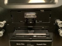
I'm a little late, but in the past month i had no time to scan. Now I'm reading all the new posts and came to #83. Here I came to Omegas #573 and read about skipping. I have the same issue and just want to make clear for me ( because I'm german ) what you mean with "the spring". Your picture points on the screw. Do you meant to get rid of the screw or to get rid of the whole "metal thing" ?
I'm a little late, but in the past month i had no time to scan. Now I'm reading all the new posts and came to #83. Here I came to Omegas #573 and read about skipping. I have the same issue and just want to make clear for me ( because I'm german ) what you mean with "the spring". Your picture points on the screw. Do you meant to get rid of the screw or to get rid of the whole "metal thing" ?
Which software version you depend on ?After scanning varios Kodahchrome films, here are my white balance numbers: 321,176,145. No blue snow and no reddisch faces any more. Thank you OdanO!
The plastic posts are held by screws that are easily removed once you have separated the case.Hi, this looks like an easy way to protect the filmbase. I have managed to deassemble the hull and I see now that the plastic-rod, wich You have added the nylon wasker and spacer on, kan be loosened from the inside.
bow do I securely disconnect the two flatcables?
brg
Claus
So the two ribbons you see in that picture---the narrow one goes to the button control panel on top of the unit. Before you pull apart the halves further, move that top panel to the other half so that you only need to disconnect the wider ribbon to the back half. I use masking or painter's tape to hold that button panel in place so that it does slide out.
That wider ribbon uses a “pull out” black tab—don’t try to pull the tab out more than you need to—light pressure on both sides of the tab should release the ribbon.
Last edited:
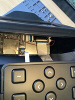
Thnx for advise, it worked great. I have also removed the cover to the sensor and lens. I was thinking about if I should lower the lens by 12 mm as mentioned earlier on this forum. But there is a plastic wall in the backgroud. Does this background cover the screws, that holds the sensor?
and I took a photo of the sensor. Can I recognize if my Reel is the modelD by the brand of sensor?
My S/N starts with H28251488K******. I have not tried to flash a new firmware yet, but I am more than willing to contribute with tests if it can help the mission

and I took a photo of the sensor. Can I recognize if my Reel is the modelD by the brand of sensor?
My S/N starts with H28251488K******. I have not tried to flash a new firmware yet, but I am more than willing to contribute with tests if it can help the mission
Attachments
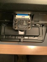
Hi. I was thinking about lowering the lens and sensor like You have done. But how do You reach the screws? I added a photo with my sensor and lens ?I am still in utter admiration for the energy and dedication you all are putting into fabricating a firmware that helps us getting a decent picture quality out of a seemingly unsatisfying consumer product!Thank you for that!
I am currently into the hardware side of things and I tried an el cheapo solution for enhancing the resolution my Kodak is getting with its stock lens.
Simply Because I didn't want to spend another 100 € for a new lens, I thought about just bringing the camera closer to the film strip.
After testing a possible distance, where I still was able to focus, I settled on 12 mm.
Which is about the distance between the screw holes of the camera mount. That way I only had to drill four new holes into the metal plate of the scanning assembly.
View attachment 26612
After remounting the camera and connecting it again (don't worry, the ribbon cable should be long enough), I could measure how much of the plastic case below it I had to cut away. (about 5 - 6 mm)
Finally I had to modify the camera cover to fit over the lower hanging lens.
The result now looks like this (cover removed for illustration purposes)
View attachment 26614
View attachment 26615
With everything in place I refocused the stock lens to match the new height.
Compared to the effort I had put in, I am pretty satisfied with the final result, considering both resolution and overall look of the modification.
Here is a comparison of before and after - both in 1600x1200 (max zoomed out)
The effective resolution is now at 1152x864, with a small margin around the actual frame.
View attachment 26618
Here is another screenshot of the capture. Given that the actual movie isn't the highest quality, I am still happy with how it turned out
View attachment 26619
Here's my final summary:
Advantages
- sourcing of a fitting new Lens unnecessary (cost saving)
- absolutely no 3D-Printer or other special tools needed,
just a sharp 4 mm drill, a screwdriver and a knive or a dremel- minimal modification of the case (time saving)
- all can be done within about one hour
- no change of the overall aesthetic of your scanner
- mostly easily revertable, if in the future you should decide to go the full mile (with a new lens)
Disadvantages
- not the full possible resolution of 1600x1200 (only 1152x864)
- the lid of the transport mechanism doesn't open completely
(but still high enough to easily thread the movie through)
I would love to hear your comments about my approach. For me personally it's totally sufficient, especially in connection with the modded firmware and considering the cost and time savings.
brg Claus
Attachments

This approach involves drilling new holes into the chassis that the lens board mounts to. I think getting the 12mm macro lens is the better way to go, and keeps the alignment in place. You do have a Type D unit, as that sensor board is stamped 2025.Hi. I was thinking about lowering the lens and sensor like You have done. But how do You reach the screws? I added a photo with my sensor and lens ?
brg Claus
i'm sorry i didn't take pictures of the whole process, i hope i can make it a bit clearer:Hi. I was thinking about lowering the lens and sensor like You have done. But how do You reach the screws? I added a photo with my sensor and lens ?
brg Claus
you have to completely unscrew the scanning unit from the case.
there are like 8 screws that are screwed into the plastic.
first, carefully disconnect the ribbon cables. you have to unlock the connectors.
then remove the screws marked green, so that the pink metal plate comes off.
this holds the scanning assembly together. after that, remove the red marked
screws, to separate the metal plate and the yellow motor cage, together with
the transport mechanism.
you should now be left with only the pink plate, to which the camera module is attached.
remove the four screws that holds it in place and you only have the plate, ready to be drilled.
Last edited:
Which software version you depend on ?
I `m using Version A77. Old Kodak Chrome film from e.g. 1947 may need modification of colours in editing, There is too much green. I use Vegas pro 20.
Last edited:
@Deano, thanks again for sharing this! I was able to incorporate several components of this (including your spacer design, lens cover, and your recomendations for lens tube & locking ring) into my already-modified scanner. I am now able to get much better focus with my 12mm lens! Now I just need to get the dust removed off the sensor (with the product that 0dan0 recomended earlier). Then, the re-scanning shall commence!Hello everyone,
Just before the New Year, I received the components necessary for upgrading the lens on my Type C system. Since then, I've finished all of the physical upgrades, and thought everyone might find my process informative. My first approach was to utilize the part files 0dan0 had graciously provided, but as I progressed, I decided to design my own parts. I've got FDM and MSLA part printing capabilities at home, so iterating the designs was relatively simple and they did the job I needed.
At the end, I've put together a comparison image attempting to show the detail improvements I see with all of the physical upgrades. I hadn't seen this type of comparison before, and I found it helpful to qualify the investment I've put into this humble consumer scanner. I hope that it helps answer questions about whether or not upgrading the lens is worth it (I'm convinced!). Note however that I've only been using V6.6 firmware up to this point and that's reflected in the comparison image. I'm looking forward to trying the newest FW versions in the coming weeks!
Hardware Upgrade Process
Accessing the lens and image board- I've seen stills from others, but I thought a quick video would be helpful.
View attachment 25962
Removing stock lens- The adhesive fixing the focus on the original lens and preventing its removal appears to be a type of hot glue stick. Applying some heat (high heat not necessary) for about a minute softened it enough to pull off with pliers.
View attachment 25963
View attachment 25964
Removing the image board- Remove the four outermost screws. I measured the screws holding the board to the system and concluded mine are M1.7. Probably self threading. An unusual size. I stuck with M1.7's for better or worse. You might get away with slightly larger screws if they're easier to procure.
View attachment 25965
View attachment 25966
View attachment 25967
Removing the image board from the ribbon cable- I used a spudger to rotate the black retention feature up. The cable then easily slips out. Be careful lifting the retention feature, it's fragile and not meant for repeated actuations
.
View attachment 25968
View attachment 25969
Removing enclosure material above the image board- The new lens will need to relocate the image board higher from the film. Unsure how high to go, I printed 0Dan0's two piece riser and measured 9mm when I put them together. So I removed 9mm of material from the enclosure as well. Ultimately I used my own riser design which was only 7mm's high. I presume 7mm removal would be fine as well, although the 9mm's gave me a bit more room to fold the ribbon cable out of the way when reinstalling.
I didn't want to remove the front enclosure to perform the cutting, and I didn't want to use any power tools which in my hands would have been a disaster. Instead, I kept the unit assembled, tucked the ribbon cable out of the way, and used some metal tape that's been in my family for decades to act as a template for hand scoring the opening. I used a carbide tipped tool used by scale modelers to scribe panel lines in their models to start the process, removed the tape, then transitioned to an Exacto knife to finish cutting through. It took me about half an hour to cut through. Thankfully with little drama other than the scratches I caused when my scoring tool slipped out of the groove when I wasn't being careful enough.
View attachment 25972
View attachment 25973
View attachment 25974
Installing new lens (https://www.rmaelectronics.com/azure-photonics-azure-1228mac/), 7mm extension ring (https://www.m12lenses.com/7mm-Metal-Extension-Ring-for-M12-Mount-p/pt-erm12-700m.htm), and lock ring (https://www.m12lenses.com/M12x0-5-Lock-Ring-CNC-Machined-Aluminum-p/pt-lrm12-2.0m.htm) onto the image board-
I don't have specific photos showing the installation of these components onto the image board, but it's relatively simple. First screw the 7mm extension ring onto the existing plastic lens mount. Be carful screwing it in. the metal threads of the extension ring can easily strip the plastic threads of the lens mount. Next screw the lock ring onto the lens, then screw that assembly onto the installed extension ring.
Re-attach ribbon cable to the image board
View attachment 25985
Installing riser- I decided to design a one-piece riser for elevating the lens/image board. I made 4mm, 5mm, 6mm, 7mm, 8mm, and 9mm versions. The only one that didn't give me fits trying to focus was the 7mm design. It's printed on my MSLA printer to retain the small alignment pin details.
View attachment 25986
View attachment 25987
I purchased M1.7 x 12mm screws for installation. They're tough to find, but I found a supplier on eBay. Unfortunately their thread does not match the original screws, but they bit into the existing unit's plastic threads fine.
View attachment 25988
View attachment 25989
Reduced aperture cap- I printed a 3mm aperture hole cover for the lens per recommendations made by 0dan0. Printed in ABS which gives it just enough stiction to hold onto the lens well. I didn't really appreciate how useful this would be until I tried getting a good focus with the new lens. It's helps immensely!
View attachment 25990
View attachment 25991
Backlight mask- Taking inspiration from 0dan0's mask, I built this piece to help mask any light bleed from outside the film edges. It fits snuggly in the film strip opening and appears to provide a bit of contrast improvement. I'm looking to do another version where it fits behind the film instead of above it.
View attachment 25992
View attachment 25993
Backlight Mask-Below Film Alternate- This is an alternate idea for masking the backlight edges. It fits below the film inside the backlight opening. The two walls of the mask should run parallel to the film. The walls are meant to aid in pressing the mask into place (it's a mild press fit), and aid in removing it from the unit with your fingers or tweezers. I haven't compared its effectiveness with the door attached mask, but I would expect it to be very similar. I'm actually using both masks which again I have no proof makes any difference. Your choice!
View attachment 26587
View attachment 26588
View attachment 26589
View attachment 26590
Cover-Lastly, inspired by Federico's mods, I decided to design a cover for the lens and image board. I rather like looking at the exposed lens and its components, but there's a benefit to keeping it all covered and protected. It's a resin MSLA part finished and painted black.
View attachment 25995
View attachment 25996
View attachment 25997
Image comparisons- Lastly, I put this image together to better understand in what manner and quality all of these hardware (and FW 6.6) enhancements provided. I focused on one subject in a particular frame which had some decent focus. Each of the comparative images are at 1:1 pixel scale to each other. The last image to the far right is an image I took of the film frame taken through an inexpensive pocket microscope (Carson Microflip Pocket Microscope). I was trying to find a method to better see the film's grain to compare with the scanner captures. If I had a higher resolution camera on my iPhone, I probably would have captured the grain even better, but I think it conveys what I needed it to ok. I originally thought this was going to be an expensive path to follow, but was pleasantly surprised at how inexpensively and well this turned out.
I'd appreciate your thoughts!
Full frame with area of interest highlighted. This image was captured with the Reels original 2.0 FW and stock lens.
View attachment 25998
Comparative images (copy full image to zoom in)
View attachment 26002
Carson Microflip Pocket Microscope
View attachment 26001
Thank you everyone for the amazing work you put into improving this device!
3D (STL) models of my parts are attached to this document.
Like you, I found some M1.7 x 12mm screws on eBay. They took a while to ship from China, but because they shipped so many of them, I'd be happy to mail out a set to those who are following this design. Just message me and we'll set something up.
Last edited:
Hello. Thanks in advance for your help. I'm attempting to use 0dan0's 7.7.1 version A variant on my Kodak Reels. I've attached the serial number and the startup screen on the scanner. When I start a scan, it goes through all of the motions of scanning, but once it is done (4.5 hours later), there are no scanned video files on my memory card, which is a 128GB card. I have been able to use mac84's 1440p version, which does produce video files. I've also tried other versions (7.4 and 7.3) and they give the same result, no video files.
So my questions are:
1. Based upon my serial number, is the A variant the correct one?
2. Am I doing something wrong?
3. What else should I try to do to get this working?
Thanks again,
Chris
So my questions are:
1. Based upon my serial number, is the A variant the correct one?
2. Am I doing something wrong?
3. What else should I try to do to get this working?
Thanks again,
Chris
Attachments
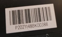
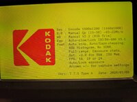
Hello. Thanks in advance for your help. I'm attempting to use 0dan0's 7.7.1 version A variant on my Kodak Reels. I've attached the serial number and the startup screen on the scanner. When I start a scan, it goes through all of the motions of scanning, but once it is done (4.5 hours later), there are no scanned video files on my memory card, which is a 128GB card. I have been able to use mac84's 1440p version, which does produce video files. I've also tried other versions (7.4 and 7.3) and they give the same result, no video files.
So my questions are:
1. Based upon my serial number, is the A variant the correct one?
2. Am I doing something wrong?
3. What else should I try to do to get this working?
Thanks again,
Chris
Use a 32GB cards or smaller, or try formatting the card as FAT32. I think the large card support was broken.
Thanks. I have an 8GB card that I used to program the scanner, but it displays this when I select capture. I'll see if I have a larger card.Use a 32GB cards or smaller, or try formatting the card as FAT32. I think the large card support was broken.
Attachments
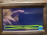
I was able to capture using a 32GB card. Thanks! However, the frame jitter is very noticeable.Thanks. I have an 8GB card that I used to program the scanner, but it displays this when I select capture. I'll see if I have a larger card.