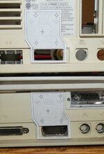
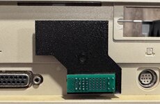
OK, I got my longer 2mm pitch header pins, as well as some round machine pin headers. The machine pin headers are a bit shorter, at about 11mm total length. The square pin headers are 19mm total length.
I wasn't sure if the machine pin headers would be a good fit, because the closest diameter I could get for that would be small enough to fit the holes on the pcb was 0.02in (0.51mm). The original pins on the HDI-45 male connector was closer to .6mm. So I wanted to take two of my test PCBs and use both type of connectors and see which one fit better. The machine pin headers weren't terribly cheap, so I only fit the minimum to get it to seat properly.
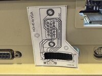
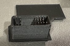
Here's the regular square 2mm pitch headers:
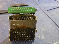
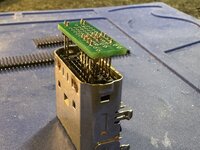
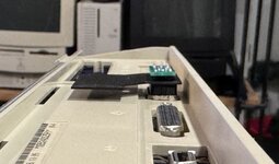
As you can see, there's plenty of room for clearing the case, as well as any 3d printed backing, and the double sided tape. May not even need to trim any of the pins down. The fit is very secure, and the addition far pins make it much harder to plug in wrong (not impossible, although without a shroud on the back side, the longer pins are going to make it hard to prevent incorrect plugging in.
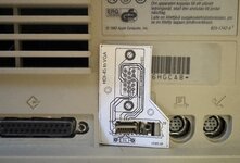
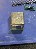
Here are the shorter 11mm machine pins. I think they will be too short to be usable. I'll have to see if I can find some with the same diameter, but with a longer total length. Unfortinately, the next size up of the ones I used are 26mm in length, and are $0.30 each. That will get costly since there should be 20 pins on each connector. The pins alone will add $7 to the cost of the adapter.
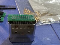
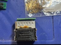
The fit is looser than the square pins. It could partially be due to the fact I only installed 4 pins. However, installing individual pins is tedious and much more time consuming than the headers that come with spacers. Even using the existing connector as a jig to align the pins, it is tough because the longer pins mean moving each individual pin to get them to slide into the PCB holes.
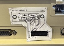
Here's the various test PCBs with standard length header, 19mm square headers, and 11mm machine pin headers:
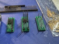
Given the looser fit, the more challenging installation, and the higher cost, I think the square pins are the right choice for me. With the longer pins, I actually am beginning to think this may allow this to even work on the 8100. We'll see when my larger PCB comes in and I can do a quick test.
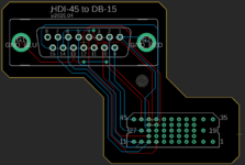
I'm hoping my test PCB with the earlier design (90 degree VGA connector going to the left, no diode, so 640x480 on this board). However, I was mainly wanting to see if my sizing would work, and the pins would be long enough for the larger PCB.
I've got some idea for a 4d printed case that I may start typing with, so more to come on that front...

