
Page Buffer Capture from Radius FPD/SE VRAM Input - First baby step to cloning Card
- Thread starter Trash80toG4
- Start date
You are using an out of date browser. It may not display this or other websites correctly.
You should upgrade or use an alternative browser.
You should upgrade or use an alternative browser.

I doubt RGBtoHDMI has the horsepower to do my rotation transform in real time. Started looking at this one:
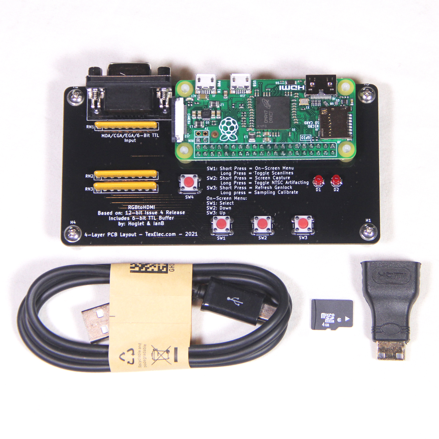
RGBtoHDMI - 6-bit TTL Edition - TexElec
The RGBtoHDMI is an excellent open project created by Hoglet67 (David Banks) and IanB (Ian Bradbury). The purpose of the RGBtoHDMI is to convert many different TTL and analog video signals from vintage systems to a modern HDMI or DVI compatible output. It uses a Raspberry Pi Zero along with a...
 texelec.com
Moved on to FPGA for speed and flexibility for future development.
Last edited:
I suppose one could take a video of the display to see if the raster is horizontal or not.Do you know that the image isn't rotated in software?
It must be horizontal according to the timing info posted at
https://68kmla.org/bb/threads/page-...t-baby-step-to-cloning-card.52646/post-594899
57.283 MHz = 17.4571862 ns
68.85 kHz = 14524.3282 ns
75 Hz = 13333333.3 ns
width = 14524.3282 / 17.4571862 = 832 pixels. (less than the active vertical height of 864 lines so this must be horizontal)
height = 13333333.3 / 14524.3282 = 918 lines.
Last edited:
The image scans as I've illustrated it.
from start, scans across 640 pixels, doubles back, drops one row . . . repeats 800+ times.
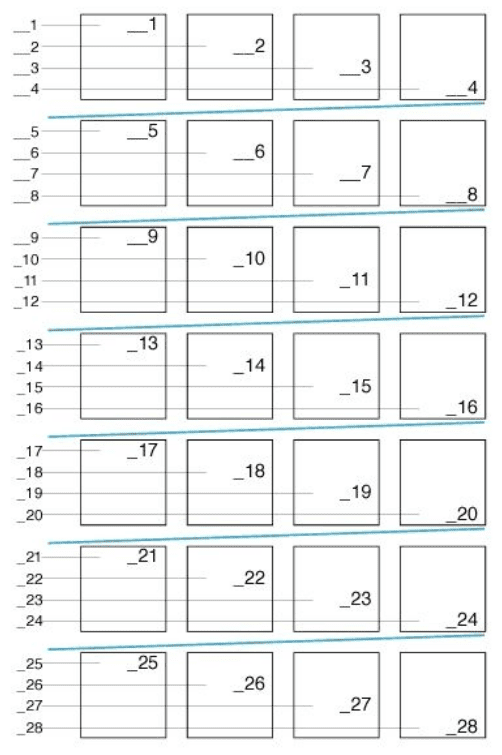
RGBtoHDMI centers the output mid-screen just as does my Extron Scaler. Neither setup supports rotation to get practical use of FPD 640x800+ output.
from start, scans across 640 pixels, doubles back, drops one row . . . repeats 800+ times.
RGBtoHDMI centers the output mid-screen just as does my Extron Scaler. Neither setup supports rotation to get practical use of FPD 640x800+ output.
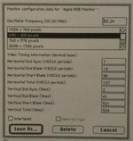
832 pixels wide = Front Porch (x pixels) - 640 Pixels - Back Porch (y pixels)width = 14524.3282 / 17.4571862 = 832 pixels. (less than the active vertical height of 864 lines so this must be horizontal)
height = 13333333.3 / 14524.3282 = 918 lines.
918 Lines = Vertical Start Blank (x lines) - 864 Lines - Vertical End Blank (y lines)
edit:
Last edited:
Poor choice of words in that sentence, he's describing the scan line in table above overall, check 24:00.21:45 "It's literally outputting scanlines less wide than they are tall."
Image is built up exactly the same way a 640x480 is built, just the aspect ratio is higher than wider. It's done in hardware in both cases..
It's exactly the same as a horizontal scanline 640x480 display. But has 384 additional scanlines making it 640x864
Handy screenshot!
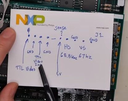

Handy screenshot!
Last edited:
Up until my last post, you were convinced the card performed rotation in hardware, and were ready to tear into your card under that assumption.
This is why I suggested dumping the frame buffer. If you get into the weeds without a high-level understanding of what's going on, you'll go down some expensive and tedious dead ends.
Rotation of a ~70KB frame buffer is trivial for even the slowest of PIs, but it's awkward to do in hardware. 1-bit graphics, VRAM serial data and monitor rasters are all row (not column) oriented.
This is why I suggested dumping the frame buffer. If you get into the weeds without a high-level understanding of what's going on, you'll go down some expensive and tedious dead ends.
Rotation of a ~70KB frame buffer is trivial for even the slowest of PIs, but it's awkward to do in hardware. 1-bit graphics, VRAM serial data and monitor rasters are all row (not column) oriented.
Last edited:
No, I've been saying all along that the card performs no rotation at all. It builds a standard horizontal scan 640x864 image that needs to be rotated to be useful on the target displays.
At present, there are no solutions for rotating the image outside of very high end systems. cloning with built-in rotation is the only option.
At present, there are no solutions for rotating the image outside of very high end systems. cloning with built-in rotation is the only option.
Ok, so what you want to build is not a faithful reproduction of the original card, but a replacement that will drive modern displays?
If so, then forget about the VRAMs, which are bound to generating raster output in one orientation.
They're probably also not easy to source anymore.
I still don't have a clear definition of what your final goal is. The intermediate steps you've laid out (like the Pi) might not be useful toward it.
If you want to build a work-alike card with HDMI output, start with an HDMI dev/eval board.
It will already have enough internal memory to make VRAMs redundant. Also, the organization of the internal memory doesn't have the same constraints as VRAM and will lend itself more easily to rotation.
Also, Radius has used software rotation: https://www.macintoshrepository.org/17294-soft-pivot-3-2-1-for-radius-pivot-display
Though software rotation on a 68000 is doing it no favors.
If so, then forget about the VRAMs, which are bound to generating raster output in one orientation.
They're probably also not easy to source anymore.
I still don't have a clear definition of what your final goal is. The intermediate steps you've laid out (like the Pi) might not be useful toward it.
If you want to build a work-alike card with HDMI output, start with an HDMI dev/eval board.
It will already have enough internal memory to make VRAMs redundant. Also, the organization of the internal memory doesn't have the same constraints as VRAM and will lend itself more easily to rotation.
Also, Radius has used software rotation: https://www.macintoshrepository.org/17294-soft-pivot-3-2-1-for-radius-pivot-display
Though software rotation on a 68000 is doing it no favors.
I think one of the goals is to be able to use the 68K driver unmodified without having to write a new driver. This driver is on disk or in a ROM on the card?Ok, so what you want to build is not a faithful reproduction of the original card, but a replacement that will drive modern displays?
I still don't have a clear definition of what your final goal is. The intermediate steps you've laid out (like the Pi) might not be useful toward it.
Exactly. We have existing drivers known to be good thru System 7.1 with version 4.4 ROMs for a VidCard that can be cloned.I think one of the goals is to be able to use the 68K driver unmodified without having to write a new driver. This driver is on disk or in a ROM on the card?
Drivers are in ROM with a tiny INIT installed in the System Folder.
VRAM capture approach was bounced off our two gurus of FPGA. They strongly suggested putting GALs and logic in the FPGA Dev. Board. The entire card can be cloned in FPGA set up to use existing drivers.
I'm doing proof of concept for that. Looks like I need to clone as much of the input side (Front End) board as necessary to hijack output. Diverting it to FPGA as opposed to the card's "Back End" using Pi
Currently buzzing the board for schematic capture as I'm wire wrapping a prototype. That'll need to be done eventually for cloning the card. At this point I'm hoping output from the four GALs would be the place to do screen capture. I'm concentrating on VRAM to GAL connections. If all I need is output from four GALs aligned with VRAM, so much the better. I could move the carrier board topside and plug it into the GAL sockets, moving them onto the carrier.
So far so good. View is solder side, need to square up ground pins.Note the curious ground line connection (Green) between VRAM and GAL. Best WAG for that would be grounding the sense line on the video connector, testing monitor connected case? Dunno . . . it's a mystery.
edit: No mystery there hadn't mirrored the pinout. The green trace is from pin 1, not ground. OOPSIE.

Last edited:
Exactly.Ok, so what you want to build is not a faithful reproduction of the original card, but a replacement that will drive modern displays?
Hence, the rotation transform mostly filling a DVI display at 1024x768, rotated to portrait orientation.If so, then forget about the VRAMs, which are bound to generating raster output in one orientation.
Was told to rework card when I proposed the project many moons ago, for me impossibru.If you want to build a work-alike card with HDMI output, start with an HDMI dev/eval board.
Indeed, Radius 64KHz FPD card is the only one of which I'm aware that can be cloned for SE PDS.Also, Radius has used software rotation: https://www.macintoshrepository.org/17294-soft-pivot-3-2-1-for-radius-pivot-display
Though software rotation on a 68000 is doing it no favors.
The epitome of 68000 Compact Mac DTP (or CAD in my case) workstations in 1987 was Radius FPD/Radius 16 Accelerator combo.
Never got the FPD, but obsessed with it to this day.
Was told to rework card when I proposed the project many moons ago, for me impossibru.
Rework it how exactly? Rotating graphic data at the bit level cannot be done by VRAMs.
If you can't work out how that's supposed to happen on paper, designing hardware is jumping the gun.
Not at all, he said the approach to take was reworking the formulas in the GALs. Figured that would require new drivers in ROM. Dropped out as it would require work far, far above my pay grade. I've been searching for that thread to post his reply.Rework it how exactly? Rotating graphic data at the bit level cannot be done by VRAMs.
Searched high and low for an available solution for image rotation at that point and came up short at the $200 range.
Not doing anything on the cloned section of the card. Frame buffer capture in its native form from somewhere on the card is rotated in the FPGA and signal goes out its HDMI/DVI. Don't really care how much of the card itself needs to be cloned to hijack signals for that. Anything short of the cable connector pins will be a win.
Designing a frame buffer capture board on a carrier, not a VidCard. I'm buzzing the board for schematic capture at present. Hoping GAL output will be the wedge I need for that at this ATM. If GALs are the way to go, carrier board prototype implementation is simplified by an order of magnitude.If you can't work out how that's supposed to happen on paper, designing hardware is jumping the gun.
Worked out the rotation transform, that's what kicked off the current edition of the project. Undoubtedly requires more horsepower than any available SBC. All I need is page buffer data capture in the top left frame.
Pi Zero 2 W is on the carrier for capturing what'll amount to every Nth frame if it even has the bandwidth/power to do the capture at all. Not sure Pi 5 can do that, much less run the rotation transform in real time. Hence, FPGA approach.
FPGA Dev. Board suggestions hover in the $100 range. FPGA itself will need to be integrated on the clone PCB if things work out.
Last edited:
The VRAMs cannot be made to rotate video.
The entire point of the GALs is to drive the VRAMs.
The VRAMs will not be a part of the final design, therefore the GALs are pointless and a waste of time. They cannot be reworked to do what you want.
The Pi also doesn't help you get any closer to the final product. It's not an intermediate step, but a dead end.
The entire point of the GALs is to drive the VRAMs.
The VRAMs will not be a part of the final design, therefore the GALs are pointless and a waste of time. They cannot be reworked to do what you want.
The Pi also doesn't help you get any closer to the final product. It's not an intermediate step, but a dead end.
Never implied VRAM could do anything like that, data inputs to VRAM were to be captured and run through the FPGA early on in the thread.The VRAMs cannot be made to rotate video.
Waiting for feedback on the viability of snooping GAL outputs for assembled page buffer data. If possible that'd be a convenient wedge.The entire point of the GALs is to drive the VRAMs.
VRAM will definitely need to be on the clone. I was hoping the data feed to them from CPU could go straight into FPGA, but that's a convoluted mess. Readbacks from CPU on FPGA powered VidCards were confirmed, so dropped VRAM capture and am moving higher up the board to the GALs.The VRAMs will not be a part of the final design, therefore the GALs are pointless and a waste of time. They cannot be reworked to do what you want.
You mentioned RAMDAC earlier? There is none, the board and output signals are entirely digital. If there were a RAMDAC, that would be the place to capture the page buffer. Haven't figured out the digital equivalent of RAMDAC on the card. That's the last best hope for capture, hoping to wedge the capture in somewhere much before that point.
As I said, I don't really care how much of the card needs to be cloned 1:1, anywhere short of the cable pins is a big win. Tacking the FPGA onto the board at that point is an acceptable, id not a desirable outcome.
VRAM will definitely need to be on the clone.
Why? VRAMs cannot be involved in a design that performs hardware rotation. It doesn't matter how you transform their inputs, they're internally fixed for row output. Prove me wrong.
I was hoping the data feed to them from CPU could go straight into FPGA, but that's a convoluted mess.
No, putting an FPGA on the system bus is much simpler than trying to decipher GAL output. Leaving them in the picture not only adds parts and expense, but bottlenecks performance. Like I said, their main purpose is to interface to the VRAMs, which are a no-go for what you want to do.
You mentioned RAMDAC earlier? There is none, the board and output signals are entirely digital. If there were a RAMDAC, that would be the place to capture the page buffer.
You were actually the first to mention RAMDAC in this thread. I know it's not a DAC and doesn't handle a palette, but it does serialize the VRAM output, which is the place that a SPI bus could capture it. Other than a fun exercise, it wouldn't be useful for much.
No need to prove you wrong, I have never said image rotation will take place anywhere but in the gates of the FPGA, You've been assuming that I'm trying to do things I've never suggested. Not doing rotation in VRAM, not in GALs, no rotation will be done ANYWHERE on whatever portion of the board that's required to get the page buffer/unrotated raster image into the FPGA.Why? VRAMs cannot be involved in a design that performs hardware rotation. It doesn't matter how you transform their inputs, they're internally fixed for row output. Prove me wrong.
Again, I do not care if I wind up cloning the entire card 1:1 with modernized, but exact function components do do exactly what my cards do at present.
If you want to have a go at it the FPGA will be connected to the SE PDS, as will be the data from the FPD card that needs to be rotated. Hoping someone will be able to clone the Radius 16 Accelerator in the FPGA paired with a streamlined. FPGA based FPD clone.No, putting an FPGA on the system bus is much simpler than trying to decipher GAL output. Leaving them in the picture not only adds parts and expense, but bottlenecks performance. Like I said, their main purpose is to interface to the VRAMs, which are a no-go for what you want to do.
Performance is not a problem, I'm aiming to capture one frame and then feed it to the screen while the next frame loads into the other half of the double buffer setup. That's a single screen draw delay. Reply to that approach came back:
"And really, you probably don't even need two buffers. Just use a dual-ported BRAM and read from one port while you're writing to the other. I'm sure some people might complain that you'll see screen tearing and other artifacts if you don't double-buffer . . ."
Indeed, but used it in describing how Vampire Video is set up in IIci and IIsi, nothing to do with the FPD other than as a model for describing the back end of the card..You were actually the first to mention RAMDAC in this thread. I know it's not a DAC and doesn't handle a palette, but it does serialize the VRAM output, which is the place that a SPI bus could capture it. Other than a fun exercise, it wouldn't be useful for much.
Wherever the full frame data or serialized input for the digital equivalent of RAMDAC on the card can be had, that's exactly what I need to feed to the FPGA.
Last edited: